The essentials at a glance
- It is the bridge between a controller and the field, not just a connector or a card.
- Digital, analog, and smart I/O solve different problems and should not be treated as interchangeable.
- 24 V DC control wiring is common in industrial panels, while loads may still run on AC or higher-power DC.
- Good design depends on isolation, grounding, cable routing, and clear point naming.
- Remote I/O and IO-Link reduce hard wiring and give better diagnostics than plain point-to-point wiring.
- Most faults come from signal mismatch, poor common reference, or weak commissioning discipline.
What an input/output device actually does
In practice, people use the term loosely for anything that sits between the controller and the field. An I/O device may be a simple input card, a remote terminal block, a smart sensor interface, or a compact module mounted on a DIN rail. The important thing is the job it performs: it translates real-world electrical conditions into data the controller can read, and it translates control decisions back into electrical action.
I usually explain it like this: inputs tell the system what is happening, outputs tell the system what to do next. A limit switch, pressure switch, or proximity sensor becomes an input. A solenoid valve, contactor coil, indicator lamp, or motor starter becomes an output. That split sounds obvious, but it is the foundation of every reliable panel and machine control scheme.
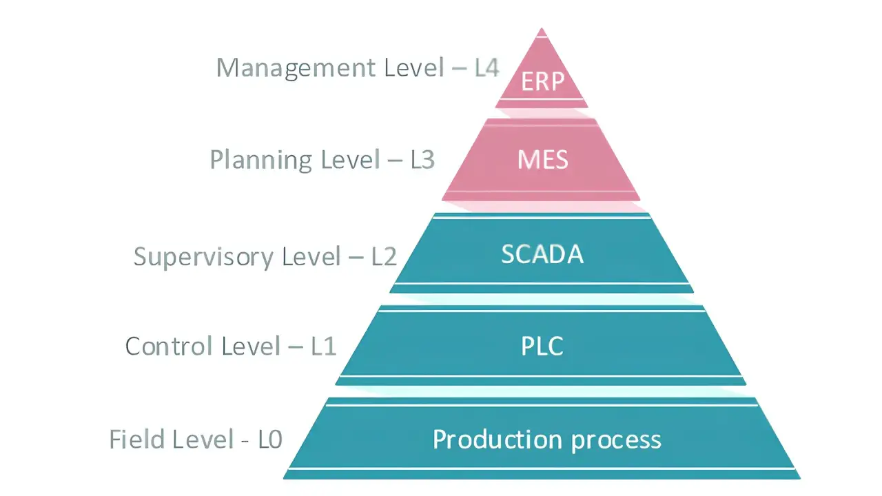
In UK electrical systems, the separation between control and power is especially useful. The control side is commonly kept at low voltage, often 24 V DC, while the load side may involve mains voltage or three-phase equipment. That separation improves safety, makes testing easier, and gives maintenance teams a cleaner fault boundary. Once that role is clear, the next step is separating the signal families that sit on top of it.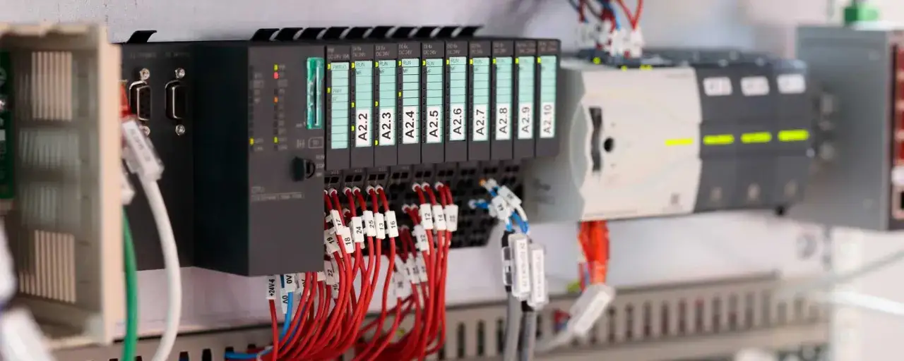
The signal types that matter most
Not all I/O is the same, and treating it that way is where a lot of poor design starts. The three families I pay attention to most are digital, analog, and smart networked I/O. Each one solves a different problem, and each one has its own wiring and troubleshooting rules.
| Signal type | What it carries | Typical examples | Why it is used |
|---|---|---|---|
| Digital | On/off state | Pushbuttons, limit switches, photoelectric sensors, relay coils | Simple, cheap, fast, and easy to diagnose |
| Analog | Continuous value | 0-10 V, 4-20 mA, temperature and pressure transmitters | Best when the controller needs a measured range, not just a yes/no answer |
| Smart networked I/O | Data plus diagnostics | IO-Link sensors, intelligent actuator modules, distributed field nodes | Useful when you want parameter changes, fault data, and less manual wiring |
Digital signals are still the workhorse of industrial automation because they are easy to trust. A 24 V DC sensor telling a PLC that a part is present is usually far easier to commission than an elaborate fieldbus node that has been configured badly. Analog signals are more sensitive, but they solve a different class of problems. A 4-20 mA loop is especially practical when the signal has to travel farther or through a noisier electrical environment, because it is less affected by voltage drop and cabling issues than a simple voltage signal.
Smart options are where 2026 practice is moving. IO-Link, for example, keeps the familiar point-to-point wiring model but adds bidirectional data exchange, which means you can read diagnostics, adjust parameters, and spot sensor degradation earlier. That matters in smart manufacturing because the useful gain is not just convenience; it is fewer hidden faults and less time wasted chasing intermittent problems. Those signal choices shape the wiring, shielding, and cabinet layout that follow.
How it fits into an electrical system
I think the cleanest way to understand I/O in an electrical system is to follow the signal path from field device to controller and back again. On the input side, a sensor generates or switches a signal. That signal passes through terminals, protection, and sometimes isolation or filtering before the controller sees it. On the output side, the controller drives a load directly or through an intermediary such as a relay, contactor, or solid-state output stage.That sounds simple, but the details matter. A few of the design decisions that make the biggest difference are:
- Isolation, which helps keep faults and electrical noise from spreading across the system.
- Signal conditioning, which shapes or protects the signal before the controller reads it.
- Grounding and shielding, which become critical for analog signals and noisy machine environments.
- Power segregation, which keeps output loads, control supplies, and sensitive measurement circuits from interfering with one another.
- Fuse and protection strategy, which limits the damage when a cable shorts or a field device fails.
Choosing the right I/O architecture for the job
The old assumption was that everything should sit in one cabinet, close to the controller. That still works, but it is not always the best answer. Remote and distributed I/O are often a better fit when the machine is large, the cable runs are long, or you want the wiring to be easier to maintain. I generally compare three architectures: local rack I/O, remote or distributed I/O, and smart field-level I/O.
| Architecture | Best for | Strength | Trade-off |
|---|---|---|---|
| Local rack I/O | Compact machines and short cable runs | Simple, fast, familiar | More cabinet wiring and less flexibility when the machine grows |
| Remote or distributed I/O | Long machines, cells, and multi-zone plants | Less copper, shorter field wiring, easier expansion | Depends on network health and good address management |
| Smart field I/O | Diagnostics-heavy or highly modular systems | Better visibility, parameter changes, faster maintenance | More upfront planning and stronger discipline around device naming |
If the application is a compact skid, local I/O may still be the best answer because simplicity wins. If the plant is spread out, remote I/O usually saves time during installation and later maintenance. If the cost of downtime is high, smart field I/O often pays for itself through diagnostics alone. In my view, the right choice is rarely about fashion; it is about cable length, maintenance access, noise environment, and how often the machine will be expanded or reworked. With the architecture chosen, the remaining failures are usually the predictable ones.
Mistakes that cause bad readings or failed outputs
The same failures keep showing up in panels and machines because they are easy to make and easy to overlook during build. I see five in particular that are worth calling out early.
- Mixing up sourcing and sinking. A sensor and an input card must agree on current direction, or the point will never behave properly.
- Assuming all 24 V devices are interchangeable. A 24 V DC sensor, a 24 V AC coil, and a 24 V output stage are not the same thing.
- Ignoring cable routing. Analogue lines run beside VFD output cables are asking for noise problems.
- Underestimating load current. Output points, relays, and terminals all have limits, and inrush current can be very different from steady-state current.
- Skipping diagnostics. If the system can tell you a sensor is dirty, disconnected, or out of range, do not design that information away.
There is also a subtle timing issue that catches people out. A controller reads inputs on a scan cycle, so a very short pulse can disappear before the software sees it. That is why high-speed counters and proper event handling matter on fast machines. I would rather build a little extra detection capability into the panel than rely on luck later. Before you sign off a panel, there are a few discipline checks that save hours later.
What I would standardise before commissioning
When I am responsible for the handover, I standardise the point list, the naming scheme, and the wiring style before anyone calls the job finished. That usually means a few practical rules:
- Leave 10-20% spare I/O capacity where the budget and panel space allow it.
- Label every field wire, terminal, and channel so faults can be traced without guesswork.
- Test each input and output with the real load, not just a simulation or a lamp test.
- Document normal readings, alarm thresholds, and expected fail-safe states.
- Check grounding, shielding, and common references before chasing software faults.
That level of discipline is not over-engineering; it is what keeps a control system maintainable six months after the install team has left. In electrical systems, the value of good I/O design is measured less by how impressive it looks on day one and more by how quickly a technician can isolate a fault on day one hundred. That is the standard I would aim for, because it is the one that actually protects uptime.