The line or load on top of switch question matters because a wrong assumption can leave a light dead, a smart switch miswired, or a circuit unsafe to test later. In practice, the real issue is not the physical top of the device; it is identifying the incoming supply, the outgoing switched leg, and any terminals the manufacturer has assigned a specific function. I’m going to show you how I separate those jobs, what changes between common switch types, and where the UK wiring layout can mislead even experienced DIYers.
Key takeaways at a glance
- Top and bottom are not a universal rule. Terminal position alone does not tell you line or load.
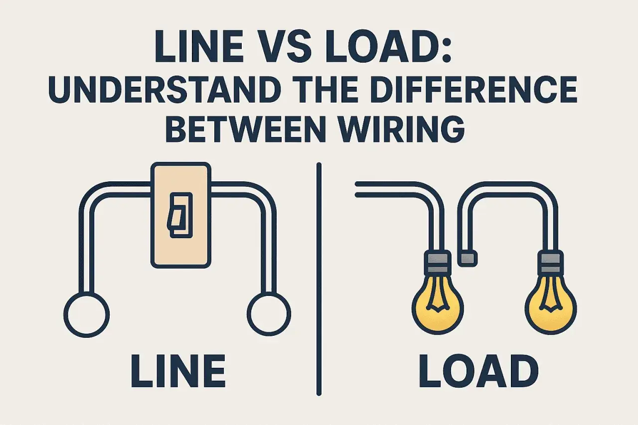
- Line means incoming supply. Load means the conductor feeding the lamp, fan, or other downstream device.
- On a basic mechanical switch, the labels matter more than the layout. COM, LINE, LOAD, L1, and L2 are the clues to trust.
- UK switch boxes often use a switched live. A blue conductor may be sleeved brown and used as live, so colour alone is not proof.
- Smart switches are less forgiving. If the device is labelled LINE and LOAD, follow the manual exactly.
- Safe isolation is non-negotiable. Prove the circuit dead with proper test equipment before touching conductors.
line or load on top of switch
What line and load actually mean
In simple terms, line is the incoming live supply and load is the wire that carries power onward to the thing being controlled. On a light switch, that usually means line comes from the supply side of the circuit and load leaves the switch toward the lamp or appliance. The switch does not create power; it only opens or closes the path between those two points.
That sounds obvious until you open a real switch box. In a UK lighting circuit, you may see a permanent live, a switched live, a neutral bundle, and the earth conductors, or you may find a much simpler two-wire switch drop with no neutral present. The same words still apply, but the actual conductors in the box can look nothing like a textbook diagram.
I use one practical rule here: line is the conductor that is live before the switch is operated; load is the conductor that becomes live only after the switch closes. Once you understand that split, the rest of the wiring question becomes much easier to reason about, especially when the next section shows why the physical top of the switch is not the answer.
Why top and bottom are not a rule
Manufacturers do not standardise “top terminal = line” across every switch. Some devices label the common terminal clearly, some use darker screws, some use COM and L1, and some smart devices mark LINE and LOAD explicitly. The switch body can also be mounted upside down, rotated, or installed in a different accessory frame, which makes a “top” assumption even less reliable.
On a plain mechanical one-way switch, the two terminals are simply the contact pair that gets opened or closed. On that kind of device, the circuit often works either way around, but I still prefer to follow the marked common or line terminal whenever one exists. Once electronics are involved, that casual approach stops being safe. Indicator lights, dimmers, motion switches, timer switches, and connected controls often need the supply on a specific terminal and can fail or behave oddly if you guess.
The mistake I see most often is people treating terminal position as function. It is a visual shortcut, not a wiring principle. If the device label and the circuit diagram disagree with the physical position, the label wins. That is the point where it pays to identify the feed properly before moving on to the actual wire tracing.
How I identify the live feed safely in a UK switch box
Before I identify any terminal, I isolate the circuit at the consumer unit and prove dead with proper test equipment. Electrical Safety First recommends a proprietary test lamp or two-pole voltage detector for proving dead, and HSE guidance is clear that unsafe assumptions with live circuits are a bad idea. Non-contact voltage sticks are not enough for this job.
Once the circuit is safely isolated, I look at the switch rather than the wall plate shape. If I see a terminal marked COM, that is usually the common connection. On a one-way switch, that is commonly the feed side or the side used for the incoming live depending on the manufacturer’s design. On a two-way arrangement, COM is still the common terminal, but the other two terminals are the strapper links between switches rather than a simple line and load pair.
Colour helps, but it does not finish the job. In UK lighting work, a blue core may be re-identified with brown sleeving and used as a live conductor, so I never trust colour by itself. I treat the sleeving, terminal label, and circuit layout as a set. If one of them does not fit, I stop and verify again.
That logic becomes even more important when the switch is not a basic one-way device, because the terminal meanings change with the switching method.
What changes with one-way, two-way, and smart switches
Different switch types use the same words differently, so I prefer to map the function instead of memorising a fake universal rule. This table is the quickest way to keep the roles straight.
| Switch type | What the terminals usually mean | Can you trust the top terminal? | What I check first |
|---|---|---|---|
| One-way mechanical switch | COM is the common connection; L1 is usually the switched output | No | Terminal marking, existing wire position, circuit diagram |
| Two-way switch | COM, L1, and L2 are used for the common and two strapper conductors | No | Which switch takes the feed, and which wire is the switched leg |
| Smart switch or dimmer | LINE, LOAD, NEUTRAL, and sometimes TRAVELLER are explicitly defined | Definitely no | Manufacturer instructions, because internal electronics may require a fixed orientation |
| Illuminated or locator switch | May need a specific line and load arrangement for the indicator to work correctly | No | Wiring diagram and load rating |
For UK readers, the biggest practical difference is that two-way switching is common in hallways, staircases, and landings. That means you can’t assume every switch box contains a neat incoming live and outgoing load pair. Sometimes the feed enters one box and the switched live leaves the other, and sometimes the box you are opening only contains one half of the switching arrangement. Once you have that in mind, the wiring starts to make sense instead of looking random.
Smart switches are the other place where people get caught out. These devices are often less tolerant of “close enough” wiring because they need a neutral, a line feed, a load connection, or all three. If the instruction sheet says a specific terminal is LINE, I do not reinterpret that as “the top one” or “the one that looks similar.” I wire it exactly as specified.
Common mistakes that create bad readings or unsafe wiring
Most miswires around switch terminals come from a handful of predictable errors. I see the same ones repeatedly:
- Assuming the top screw is the feed. This is the classic shortcut, and it is unreliable.
- Confusing a neutral with a load conductor. In a UK switch box, neutral may be absent, bundled elsewhere, or only present for smart devices.
- Ignoring re-identified blue conductors. A blue core sleeved brown is often being used as live, especially in lighting circuits.
- Swapping COM and a strapper on a two-way switch. The circuit may still seem “sort of” functional, but the switching logic becomes inconsistent.
- Relying on a non-contact tester alone. It is useful as a quick indication, but not as a final proof of dead.
- Skipping the manufacturer diagram on smart devices. Internal electronics can make terminal orientation matter in a way a basic switch never does.
There is one broader point here: when a switch box does not look tidy, that is usually a signal to slow down, not to improvise. A box full of mixed colours, old sleeving, and extra conductors often means you are looking at an installation history, not just a current wiring job. The next section is where I draw the line and stop treating it as a casual DIY task.
When to stop and call a qualified electrician
I would stop and hand the job to a qualified electrician if the switch box does not match the expected layout, if the labels are missing or damaged, or if the circuit includes a smart control that needs a neutral you cannot confidently identify. I would also stop if there is heat damage, brittle insulation, loose conductors, corrosion, or signs that the installation has been modified several times already. Those are not cosmetic issues; they affect safety and reliability.
UK guidance around safe isolation is written for a reason. Working near electricity should be planned, isolated, tested, and only then touched. In practice, that means more than flipping a breaker and hoping for the best. If you cannot prove dead with proper equipment, or if the switch circuit is part of a larger control system, the time you save by guessing is rarely worth the risk.
For industrial automation and smart building work, that caution matters even more because the switch may be one part of a wider control chain rather than a simple lamp interrupter. Once control logic enters the picture, the consequences of a wrong terminal choice are broader than a single light not turning on. That is why I always go back to the labels, the diagram, and the measured state of the circuit before I reconnect anything.
The safest working rule when the labels are unclear
My working rule is simple: never use terminal position as proof of function. I identify the line by tracing the incoming live supply, I identify the load by tracing the conductor that goes to the controlled device, and I confirm everything against the device’s markings before restoring power. If the switch is a basic mechanical type, that process is usually straightforward. If it is a two-way, smart, or illuminated switch, the same process is still the right one, but the circuit logic takes a little more care.
If you want one compact checklist, this is the version I rely on: isolate, prove dead, read the markings, trace the conductors, keep an eye on re-identified cores, and only then re-energise and test. That approach is slower than guessing, but it is also the difference between a clean installation and a recurring fault.
In other words, the answer to which terminal is line and which is load is not “top” or “bottom” by default. It is whatever the circuit design and the device label say it is, and on a 230V UK installation, that is the only answer I trust.