The practical value of a variable frequency drive application is rarely just about speed. In motion systems, a drive is often the difference between a motor that merely runs and one that actually follows the process, shaping acceleration, torque, flow, and wear in the same step. In the sections below I’ll cover where VFDs fit in industrial equipment, how they compare with servo systems, and what separates a useful installation from a noisy, underperforming one.
The practical picture at a glance
- VFDs control motor speed by varying frequency and voltage, so the motor matches the process instead of running flat out.
- They are strongest on pumps, fans, compressors, conveyors, mixers, extruders, and other loads that do not need constant full speed.
- In motion control, they are excellent for speed and torque regulation, but they do not replace a servo system when precision positioning or tight synchronisation is required.
- Energy savings are usually best on variable-torque loads, while the most immediate non-energy gains are softer starts, less mechanical stress, and steadier process control.
- Selection depends on the load profile, motor type, braking needs, harmonics, cooling at low speed, and the communication layer around the machine.
What a drive changes inside a motor system
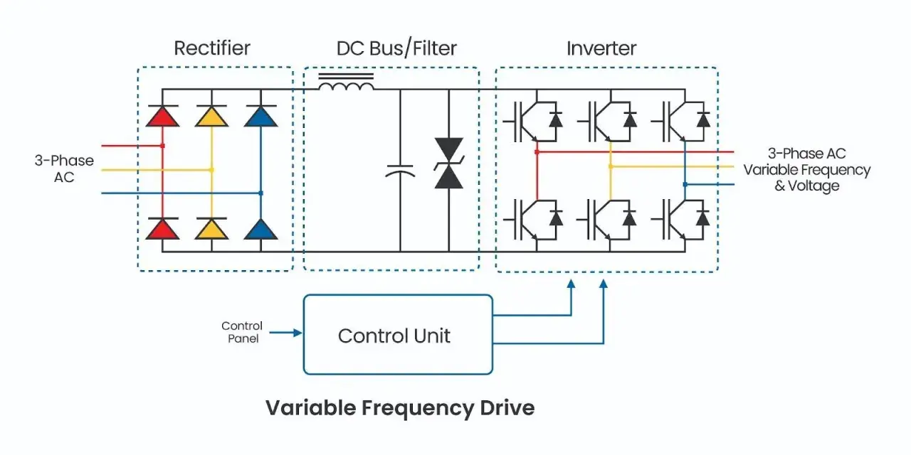
At the simplest level, a VFD sits between the supply and the motor and reshapes the power the motor receives. In the UK, where the mains supply is nominally 50 Hz, that matters because most industrial motors are built to run from a fixed-frequency source unless something actively changes it. The drive rectifies AC to DC, then inverts it back into a controlled AC waveform at the frequency and voltage the process actually needs.
I usually separate drive behaviour into three layers. V/Hz control keeps voltage and frequency in proportion and is good when the load is simple. Sensorless vector control estimates torque and speed more accurately without an encoder, which is useful when the load changes often. Closed-loop vector control adds feedback from an encoder and gives tighter speed and torque regulation, which is often the point where a drive starts to feel much more deliberate rather than merely efficient.
| Control mode | Best at | Typical use |
|---|---|---|
| V/Hz control | Simple, stable speed control with low setup effort | Fans, basic pumps, straightforward conveyors |
| Sensorless vector control | Better torque response without an encoder | Compressors, mixers, heavier conveyors, general automation |
| Closed-loop vector control | Tighter torque and speed regulation under changing load | Winders, hoists, process lines, more demanding machine axes |
| Servo control | Precise positioning and fast synchronisation | Pick-and-place, indexing, registration, high-dynamic motion |
That last row matters. I still see people try to use a drive as if it were a cheap servo, and that is where expectations break. Once the machine needs real position control, fast following, or coordinated axis timing, the drive stops being the right tool on its own. Once you understand that boundary, the application picture becomes much clearer.
Where VFDs make the biggest difference in real plants
In actual facilities, the strongest cases are not abstract at all. They show up on the loads that spend most of their life below full speed, or on systems where a softer start and better control produce immediate operational gains. In UK plants, I see the most value in water and wastewater, HVAC, food and drink, packaging, warehousing, and general process manufacturing.
| System | Why a VFD helps | What to watch |
|---|---|---|
| Pumps | Flow demand changes, so the drive can trim speed instead of wasting energy across a valve | Minimum flow, cavitation, pressure feedback, motor cooling at low speed |
| Fans and blowers | Air demand fluctuates with occupancy, temperature, and process load | Duct resonance, static pressure control, harmonics on larger installations |
| Compressors | Speed can be matched more closely to demand, reducing unload losses | Oil cooling, minimum stable speed, pressure control strategy |
| Conveyors | Smoother starts and stops reduce shock, product damage, and gearbox stress | Torque at low speed, jam detection, tension control, braking |
| Mixers and agitators | Speed control improves batch consistency and lets the process breathe instead of fighting the motor | Constant torque demand, shaft loading, seal wear |
| Hoists and cranes | Controlled acceleration and deceleration improve handling and reduce mechanical abuse | Braking, holding torque, safety logic, regeneration |
For pumps and fans, the reason the savings can be so large is not marketing language; it is physics. Flow generally follows speed, pressure rises more slowly, and power rises roughly with the cube of speed in an idealised system. That is why a modest speed reduction can make a disproportionate difference. In practical terms, a well-matched drive on a variable-torque load can often deliver 30-50% energy reduction, sometimes more, but only when the system is actually allowed to run slower instead of being forced back to full output by poor control logic.
Compressors are a little different. The win is often less about the neat cubic relationship and more about avoiding wasteful unload cycles and making pressure more stable. Conveyors and hoists, on the other hand, are often about mechanical gentleness first and energy second. That distinction matters because the same drive can look brilliant in one machine and merely acceptable in another.
How drives fit into motion control without pretending to be servos
Motion control gets confusing when people use the same word to describe very different jobs. A servo system is built for position, synchronisation, and fast response. A VFD is built to control motor speed and torque efficiently. Those are related ideas, but they are not interchangeable.
When a line only needs the infeed conveyor to stay smooth, a pump to hold pressure, or a fan to follow a setpoint, a drive is usually enough. When the machine needs to stop at a precise point, follow a master axis, or correct error in milliseconds, a servo is usually the better answer. I call that the practical dividing line: use a VFD for controlled motion, use a servo for precise motion.
There is also a middle ground. Some drives can run with encoder feedback and get surprisingly close to what many teams want from a motion axis. That can work well on winders, tension control, or certain coordinated process machines. But I would still be careful about calling it servo performance, because the loop bandwidth, trajectory handling, and timing determinism are usually still different. If the machine depends on those details, the distinction is not academic.
In hybrid lines, I often see a sensible split: a VFD handles the bulk movement, while servo axes handle registration, cutting, pick-and-place, or other precision steps. That architecture is common in modern automation because it keeps cost and complexity under control without forcing every axis into the same category. Once that is clear, selection becomes much less guesswork and much more engineering.
The selection details that decide whether the installation works
Most drive problems are not caused by the drive itself. They come from choosing the wrong control mode, ignoring the load profile, or forgetting that the motor and the panel are part of the same system. When I spec a drive, I want the answers to a short set of questions before anything else is ordered.
| Question | Practical rule | Why it matters |
|---|---|---|
| Is the load variable torque or constant torque? | Variable torque favours a VFD strongly; constant torque needs more careful sizing | It changes energy savings, thermal loading, and torque reserve |
| Will the motor run slowly for long periods? | If yes, check cooling and consider forced ventilation | A standard self-cooled motor loses cooling performance at low speed |
| Is frequent deceleration part of the cycle? | Plan for braking resistance or regeneration if inertia is high | Otherwise energy has nowhere to go and the drive will trip |
| Is the supply weak or electrically noisy? | Add reactors, filters, or harmonic mitigation early | It protects the wider installation and avoids nuisance faults |
| Does the machine need to talk to a PLC or SCADA system? | Choose a drive with the right fieldbus and diagnostics | Integration is much easier when the data layer is designed in, not bolted on later |
| Is the environment harsh? | Check enclosure rating, temperature, dust, and vibration | Drives fail faster in heat and contamination than many teams expect |
For UK sites, I also pay attention to EMC behaviour, earthing, and whether the panel is built for the real room it lives in rather than the ideal one on the drawing. A clean-looking schematic can still become a problem if the cabinet runs hot, the cable run is long, or the operator has to fight the control logic every shift. Good selection is mostly about removing that kind of friction before it starts.
The trade-offs I would never ignore
A drive can improve a system and still create new problems if the application is treated too casually. The main risks are well known, which is exactly why they are worth repeating. They are boring problems, but boring problems are the ones that cost time.
- Harmonics can distort the supply and disturb other equipment if the installation is poorly planned.
- Motor heating becomes more likely at low speed because the shaft-mounted fan cools less effectively.
- Overly aggressive ramps can stress gearboxes, belts, couplings, and product handling systems.
- Voltage spikes and bearing currents can become an issue on long cable runs or older motors.
- Wrong control mode can make the machine feel unstable, noisy, or slow to recover from load changes.
- Badly tuned PID loops can cause hunting, oscillation, and a lot of false blame on the drive itself.
There is also a simpler limitation that people often miss: not every machine spends enough time away from full speed to justify the effort. If a load runs at one fixed point all day and does not need soft starting, the business case for a drive may be weak unless the application has another clear benefit such as process stability, protection, or data visibility. That does not make the drive bad; it just means the fit is wrong.
I would be especially careful on high-inertia systems, on long conveyor trains, and on machines where the process does not tolerate speed variation gracefully. Those are the places where a VFD can help a lot, but only after the mechanical and control assumptions are worked through honestly. Once those trade-offs are visible, the next step is making the installation behave properly on day one.
What a well-commissioned drive looks like on site
Commissioning is where a promising drive project turns into a dependable one. I want the machine to start, stop, recover, and report faults in a way that the operator actually understands. That usually takes less drama than people expect, but it does take discipline.
- Record the real load profile before changing parameters.
- Set acceleration and deceleration ramps to suit the mechanics, not just the motor.
- Choose the control mode that matches the job, then verify stability under load.
- Test braking, overload protection, and fault recovery on purpose, not by accident.
- Trend current, temperature, speed, and fault history during the first operating period.
That last point matters more than most teams think. Modern drives are not just motor controllers; they are data sources. They can report current draw, torque estimate, thermal status, run hours, alarms, and sometimes energy use. In smart manufacturing terms, that makes them useful for condition monitoring, maintenance planning, and energy visibility, not just motion.
If the drive talks cleanly to the PLC or SCADA system, operators get better information and engineers get fewer blind spots. If it does not, you often end up with a powerful piece of hardware that still feels hard to manage. The best commissioning work is usually the work that makes the machine boring to run.
The checks that keep a drive useful long after start-up
My rule is simple: if the load profile changes, the process is worth studying; if it does not, the drive has to justify itself with softer starting, protection, or integration benefits. The strongest installations are the ones that still make sense after the first electricity bill, not just on the day the panel is installed.In practice, that means checking motor cooling, braking behaviour, harmonics, and control tuning again after the machine has been live for a while. It also means leaving enough diagnostic detail in the system so a fault does not become a guessing game at 2 a.m. If you do those things well, a VFD stops being a box of electronics and becomes a stable part of the machine architecture.
For UK industrial environments, especially in water, HVAC, food and drink, logistics, and general manufacturing, that is usually the right outcome: less wasted energy, cleaner motion, fewer mechanical shocks, and data that actually helps the plant make better decisions.