The choice depends on start current, overload handling, and fault level
- A motor-specific protector is built to cope with motor starting behaviour and may combine short-circuit, overload, and phase-loss protection.
- A general circuit breaker is better suited to distribution circuits and often needs a separate overload relay for motors.
- Motor starting current can reach around 10 times full-load current in the first few cycles, then drop to roughly 5 to 6 times while the rotor accelerates.
- UK and IEC datasheets matter more than the marketing name; trip function, breaking capacity, and standard compliance tell you what the device can really do.
- If a device is marked for a narrow role only, do not assume it can also serve as a main switch or a direct substitute for a standard breaker.
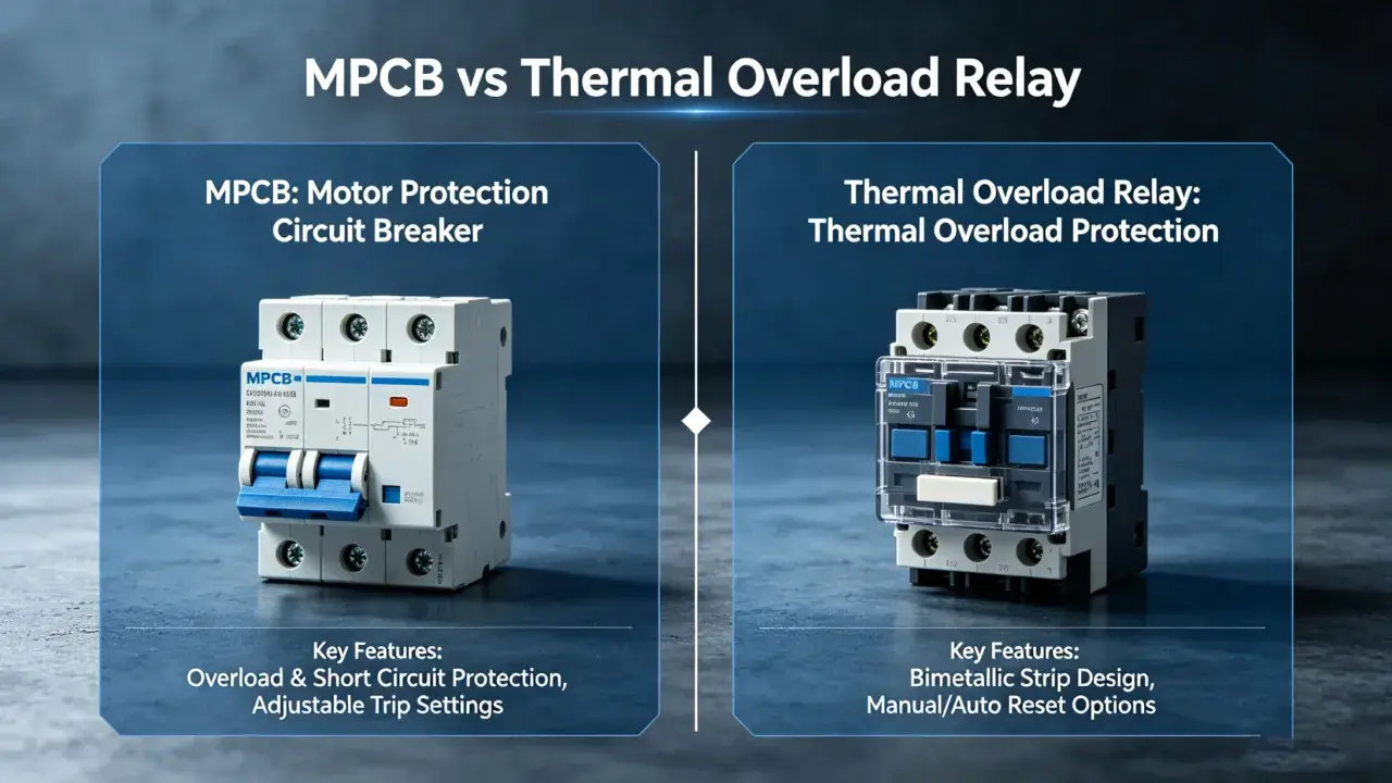
What each device is really meant to do
I treat the naming carefully, because manufacturers do not always use the same vocabulary. In IEC-style catalogues, you will often see a motor protection circuit breaker or a manual motor starter: a compact device used in motor starter combinations, usually with manual on-off control and protection against short-circuit and overload. In some North American literature, an MCP is narrower and refers to an instantaneous-trip device that protects mainly against short circuits and works with a separate overload relay.The motor-specific device
The motor-focused option is designed around the way a motor actually behaves. In many IEC/UK products, that means a thermal-magnetic device with an adjustable current range, phase-loss sensitivity, and a manual disconnect function. In simpler terms, it is trying to protect the motor and the feeder as one operating system, not just a wire run.
- Short-circuit protection acts fast when a genuine fault appears.
- Overload protection tracks sustained heating instead of reacting only to a sharp fault spike.
- Phase-loss protection helps when one phase disappears on a three-phase motor, which can cook the machine very quickly.
- Manual control is useful when the same device also serves as a local on-off point at the machine.
The standard breaker
A standard breaker, by contrast, is a general-purpose overcurrent device. In UK practice, that often means a miniature circuit breaker on a final circuit or an industrial breaker on a feeder. It is excellent at protecting distribution circuits, but it is not automatically tuned to the thermal profile of a motor.
- MCBs are commonly used on ordinary branch circuits and are often selected by curve type rather than motor duty.
- MCCBs cover larger feeders and industrial distribution, with more adjustability and higher fault ratings.
- Motor use is possible in some cases, but usually only when the motor’s overload function is handled elsewhere.
The practical point is simple: one family is shaped around motor duty, while the other is shaped around general branch or feeder protection. That difference becomes much clearer once you look at starting current.
Why motors behave differently from ordinary loads
Motors are awkward for protection devices because they do not draw current in a neat, flat line. A squirrel-cage induction motor can pull a very high inrush current for the first few cycles, then settle into a lower acceleration current before finally dropping to full-load current. In practical terms, that means the protection device must survive a burst of current without becoming blind to a real fault.
- Inrush current can be around 10 times full-load current at start-up, with roughly 5 to 6 times full-load current still present during acceleration.
- Stall risk matters because a motor that fails to accelerate keeps heating while the current stays high.
- Phase loss can damage a three-phase motor fast, even when the supply does not look completely dead.
- Frequent cycling raises heat stress and can expose a breaker that seemed fine on a single start test.
This is why a breaker that works perfectly on a heater or lighting circuit can be a poor fit on a motor feeder. A general breaker may trip too easily during start-up, or it may ride through the start but still leave the motor underprotected if the overload strategy is wrong.
That is also why I never judge a motor feeder by the curve letter alone. Curve choice helps, but it does not replace proper motor protection design.
A side-by-side comparison that makes the choice easier
When I compare devices for a UK panel, I look at the motor’s duty first and the breaker curve second. This table shows the difference that matters in practice.
| Criterion | Motor-specific protector | General circuit breaker |
|---|---|---|
| Primary job | Protects a motor feeder with motor-aware trip behaviour, often with manual control built in. | Protects a distribution or branch circuit, with motor use only where the design still fits the load. |
| Overload handling | Often integrated, or designed to work tightly with a starter and overload function. | Provides overcurrent protection, but motor thermal protection is usually not its main job. |
| Short-circuit handling | Built to clear motor faults while tolerating motor start-up behaviour. | Good at branch protection, but may nuisance-trip on motor inrush if the curve is not suited. |
| Motor start tolerance | Usually better matched to repetitive starts, stalls, and phase imbalance. | C-curve and D-curve breakers can help, but they still are not motor-specific by default. |
| Typical standards | Often appears in IEC/EN 60947-2 and IEC/EN 60947-4-1 motor-starter families. | MCBs are commonly IEC/EN 60898-1; industrial breakers are often IEC/EN 60947-2. |
| Trip threshold detail | Set around the motor’s real operating current and start profile. | IEC/EN 60898-1 uses conventional values of 1.13 x In non-tripping and 1.45 x In tripping; IEC/EN 60947-2 uses 1.05 x In and 1.3 x In. |
| Best fit | Pumps, conveyors, compressors, MCC buckets, and local machine starters. | Lighting, sockets, feeders, and motor circuits where overload protection is already handled elsewhere. |
| Common limit | Some versions are not meant to act as a main switch, so markings matter. | May need a separate overload relay or starter components before it becomes a proper motor solution. |
Once that distinction is clear, the real-world application question becomes much easier to answer.
When I would use each option in a UK industrial panel
Use a motor-specific protector when
I would reach for the motor-focused device when the circuit is doing real motor work, especially on direct-on-line starters or compact machine panels. It makes sense when the panel needs local isolation, the starter is expected to coordinate with a contactor, and the overload job belongs close to the motor rather than in a distant feeder device.
- The motor starts repeatedly during a shift.
- The load has a high inrush or a long acceleration time.
- Phase-loss protection is important because a missed phase would damage the process or the machine.
- The machine needs a compact starter with fewer separate components.
Use a standard circuit breaker when
A standard breaker is the cleaner choice when the circuit is mainly about distribution or when motor thermal protection is already provided by a drive, overload relay, or starter package. In that case, the breaker’s job is to protect the feeder and give you a sensible upstream overcurrent device.
- You are protecting lighting, sockets, auxiliaries, or general feeders.
- The motor already has a dedicated overload relay.
- You are coordinating a larger MCC or panelboard where the starter is separate from the feeder breaker.
- The breaker is part of a wider distribution architecture, not the machine-side motor starter.
Read Also: Fuses vs. MCBs vs. RCDs - Choose the Right UK Circuit Protection
Watch the VFD case
Variable-frequency drives need a separate thought process. The drive often changes the motor’s current profile, and the upstream protective device is chosen partly for the drive input and the feeder, not just the motor itself. I always check the drive manual before assuming that a conventional breaker or a motor protector is the right answer.
That is where many installations go wrong: the hardware looks close enough, but the duty case is not the same.
The mistakes that create nuisance trips or weak protection
I see the same errors repeated in motor panels, and most of them come from treating all breakers as if they were interchangeable. They are not.
- Using a C-curve breaker and calling it motor protection. A C curve can help with inrush, but it does not automatically provide the motor-specific overload or phase-loss behaviour you need.
- Picking a device by motor size alone. The real questions are starting current, acceleration time, duty cycle, and ambient temperature inside the enclosure.
- Ignoring the available fault current. For industrial breakers, I check Icu and Ics; for MCBs, I look at Icn. If the fault level is higher than the device rating, the design is wrong no matter how tidy the catalog page looks.
- Forgetting that some devices are not main switches. If the marking says the unit is not usable as a main switch, then it should not be forced into that role just to save space.
- Assuming the breaker replaces the overload relay. On many motor starters, the overload relay still does the thermal protection while the breaker handles feeder or short-circuit duties.
The biggest hidden issue is usually nuisance tripping that appears only after the machine has been running for a while. Heat, enclosure temperature, and repeated starts can shift the result enough to turn a “working” design into a maintenance problem.
My selection checklist for a motor feeder
When I spec a motor circuit, I try to keep the process brutally simple. If the device is doing the wrong job, the rest of the panel design becomes harder than it needs to be.
- Write down the motor full-load current, starting method, and duty cycle.
- Confirm whether overload protection already exists in the starter, overload relay, or drive.
- Check the fault level at the installation point and compare it with the device’s breaking capacity.
- Compare the device’s trip behaviour with the motor’s start current, not just its nameplate current.
- Verify whether the unit is intended to be a disconnect, a starter component, or only a branch protective device.
- Make sure the selected breaker or protector coordinates with the contactor, drive, and upstream protection.
If I had to reduce it to one sentence, it would be this: choose for the motor’s thermal profile first, then verify the breaker’s standards and fault rating second. That order prevents most surprises on site.
The simplest rule I use when the choice still looks close
When the decision is still borderline, I come back to one question: does the motor feeder need dedicated motor protection, or is the breaker only there to protect the upstream circuit? If the answer is motor protection, I use the motor-specific device and check the starter coordination carefully. If the answer is upstream protection, a standard breaker is usually the cleaner and more honest choice.
In practice, that rule keeps the design aligned with the real job. It avoids the common mistake of over-trusting a generic breaker on a motor load, and it also prevents overcomplicating a feeder that only needed a sensible branch device in the first place. I would rather see a panel that is slightly simpler but correctly coordinated than one that looks advanced and trips at the wrong moment.