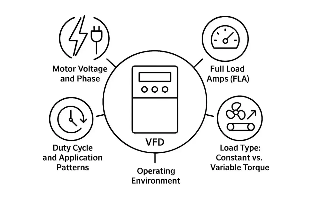
VFD sizing is really a current-and-application problem first. In motion-control work, the right drive has to match the motor nameplate, the load type, the acceleration pattern, and the way the machine actually stops. I would rather spend time on those details up front than replace a drive later because it looked fine on paper but tripped in production.
The right size comes from current, torque, and duty together
- Start with motor current, not the horsepower label, because the drive lives and dies by amps at the real supply voltage.
- Match the load type to the application: variable torque, constant torque, high inertia, or regenerative duty.
- Check overload capacity for acceleration and peaks; continuous current alone is not enough for many motion-control jobs.
- Confirm the installation conditions: supply class, ambient temperature, altitude, panel cooling, and cable length.
- Separate current limit from overload protection; they solve different problems.
The safest place to start is the motor nameplate
When I size a drive, I read the motor plate before I look at the power rating. Danfoss is blunt on this point: select the drive from current and voltage, not from horsepower alone. That matters even more in the UK, where a typical industrial supply is 400/415 V three-phase at 50 Hz, so the drive class has to match the actual supply and the motor winding connection.
| What I read | Why it matters | What I use it for |
|---|---|---|
| Voltage | The drive must match the installed supply and motor class | Choose the correct 400 V, 230 V, or higher-voltage drive family |
| Full-load amps | This is the real continuous electrical demand | Set the minimum continuous output current |
| Frequency | Shows the motor's rated base speed and operating point | Check whether the motor is being used inside or beyond its normal range |
| Service factor | Indicates extra thermal headroom the motor may tolerate | Decide whether the drive needs more than the nominal running current |
| Duty rating | Separates continuous work from intermittent loading | Match the drive to the real cycle, not just the label |
If a motor is dual-rated, I size against the current at the installed voltage. A 7.5 kW label means very little until I know whether I am looking at a 230/400 V motor or a different winding class, because the drive sees amps and volts, not shorthand. That is usually where the first sizing mistake starts. Once the nameplate is clear, the next question is how the machine actually moves.
The load profile tells you whether the drive is ordinary or stressed
Two motors with the same current can ask for very different drives. A fan or centrifugal pump usually needs modest starting torque and a gentle overload profile, while a conveyor, mixer, crane, extruder, or winding axis can demand heavy torque at low speed and repeated starts. A practical drive guide from ABB makes the same point in a different way: the drive has to cover the continuous current and the maximum current demanded by the process.
| Load type | What the drive sees | How I size it | Common trap |
|---|---|---|---|
| Variable torque | Fans and pumps, torque rises with speed | Size to running current with modest headroom | Buying heavy-duty torque capacity that will never be used |
| Constant torque | Conveyors, mixers, extruders, hoists | Use overload current and acceleration duty, not nameplate power alone | The drive trips on start or at low speed |
| High inertia | Long acceleration and deceleration, repeated starts | Check thermal capacity over the full duty cycle | One start looks fine, 20 starts an hour do not |
| Regenerative | Overhauling loads and fast stops push energy back | Add braking or regeneration capability | DC bus overvoltage during deceleration |
| Multi-motor | Several motors share one drive | Sum the full-load currents and add margin | Assuming the biggest motor is the only load |
A useful rule of thumb is simple: if the process spends most of its life below rated speed but still needs torque, I assume the drive will work harder than the horsepower label suggests. That is where a larger frame may be justified, but only if the overload and thermal ratings are also right. A bigger drive with the wrong control mode is still the wrong drive. That leads straight into overload capacity.
Overload ratings matter more than people think
For many motion-control machines, the real question is not whether the drive can run the motor, but whether it can survive the way the motor is used. A drive may be rated to run continuously at one current level and then deliver a higher current for a limited time, such as one minute every ten minutes or one minute every five minutes depending on the product class. Those overload windows are what keep a conveyor moving through a start, or a mixer from stalling when the batch thickens.
I also keep a clear line between current limit and motor overload protection. ABB’s technical note on the subject is useful here: current limit is not a substitute for the motor’s thermal protection model. In plain language, a current cap tells the drive how hard to push, while the overload model tells it how much heat it can tolerate over time. Mixing those up is a common mistake.
- Continuous current covers normal running.
- Short-term overload covers acceleration and peak torque.
- The thermal model matters when starts, reversals, or stalls repeat through the shift.
- Current limit is useful for process protection, but it is not the same as drive survival.
For variable torque loads, modest overload capability is often enough. For constant torque jobs, I expect the drive to tolerate much more, sometimes around 150 to 160 percent of motor current for a short period, depending on the application and the drive class. That difference is what separates a good fit from a drive that works only until the first hard start. Once overload is checked, the supply side can still change the answer quite a lot.
The supply and installation can change the answer
Drive sizing does not stop at the motor. I also check the supply class, the panel environment, and the braking path, because those are the places where a theoretically correct drive can still fail in the field. Many low-voltage drives are rated at about 40°C ambient and 1000 m altitude without derating, but the exact curve depends on the model; if the cabinet is warm, high, or tightly packed, I assume the published current is no longer available at full value.- Supply voltage must match the drive class, not just the motor label.
- Ambient temperature can reduce the usable current if the cabinet runs hotter than the datasheet baseline.
- Altitude reduces cooling performance, so current often has to be derated above 1000 m.
- Enclosure cooling matters if the drive is in a sealed panel with other heat sources.
- Motor cable length can add stress, EMC issues, and extra heating.
- Braking energy has to go somewhere when the machine stops quickly or overhauls the load.
If the load can drive the motor during deceleration, the problem is not usually frame size alone. It is energy handling. In that case I look at a braking resistor, a DC bus chopper, or a regenerative front end before I simply move to the next larger drive. That is especially important in motion-control equipment where stop time is part of the process, not an afterthought. Once the electrical environment is sane, the last big question is whether a VFD is even the right tool for the motion job.
A VFD is not always the right motion-control answer
For speed regulation on pumps, fans, conveyors, and many transfer axes, a variable frequency drive is a good fit. For precise position, electronic gearing, coordinated multi-axis motion, and fast torque reversals, a servo drive or a more complete motion-control architecture is usually the better choice. I see avoidable oversizing when someone tries to make a VFD solve a positioning problem; bigger current ratings do not turn it into a servo.
| Need | VFD fits well | Servo fits better |
|---|---|---|
| Speed control | Yes, especially on pumps, fans, and simple conveyors | Only if speed control is part of a wider motion task |
| Low-speed torque | Good with the right control mode and motor data | Excellent when the application needs tighter control |
| Positioning | Poor fit | Strong fit |
| Synchronised axes | Usually too limited | Designed for it |
| Rapid reversals | Possible, but braking and thermal checks become critical | Usually better matched |
If you only need tighter speed control and better low-speed torque, closed-loop vector control can help, but it is still not a positioning system. That distinction saves a lot of wasted effort. Once I know the control problem is actually a drive problem, I use a final checklist before I release the order.
The checks I use before I release a purchase order
I keep the same sequence on every project because it catches most of the expensive mistakes without turning the job into overengineering. It is short, but it is usually enough.
- Confirm the motor nameplate current at the actual UK supply voltage.
- Classify the load as variable torque, constant torque, high inertia, or regenerative.
- Check the overload class against the real start, stop, and reversal pattern.
- Verify ambient temperature, altitude, enclosure cooling, and cable length.
- Make sure the control mode matches the job, not just the motor size.
- Allow for braking energy if the machine stops quickly or overhauls the load.
If I had to reduce the whole process to one sentence, it would be this: size the drive for the current the machine draws in its hardest normal cycle, then derate it for the real installation. That approach is usually more reliable than chasing a neat kilowatt match, and it is the difference between a drive that looks right on paper and one that stays online on the shop floor.