In motion control, output load reactors are a practical way to tame the electrical stress created by fast-switched inverters and drives, especially when motor cables are long or the load changes sharply. This article explains what they actually do, when they are worth adding, how I would size them, and when a dV/dt or sine-wave filter is the better call.
The main decision is whether you need simple damping or full output filtering
- Load reactors soften the electrical edge of a drive output, reducing dv/dt, peak motor voltage, and nuisance trips.
- They are most useful on long motor leads, low-inductance motors, and multi-axis or retrofit motion systems.
- A 3% unit is usually the starting point; 5% is a deliberate choice when extra suppression is worth the added voltage drop.
- For longer cable runs, a dV/dt filter usually gives cleaner protection than a plain reactor.
- For very long runs or sensitive motors, a sine-wave filter is the heavier but more complete answer.
- Installation and cable routing matter as much as the part number; a badly placed reactor can underperform or even create new problems.
What a reactor is doing in the drive path
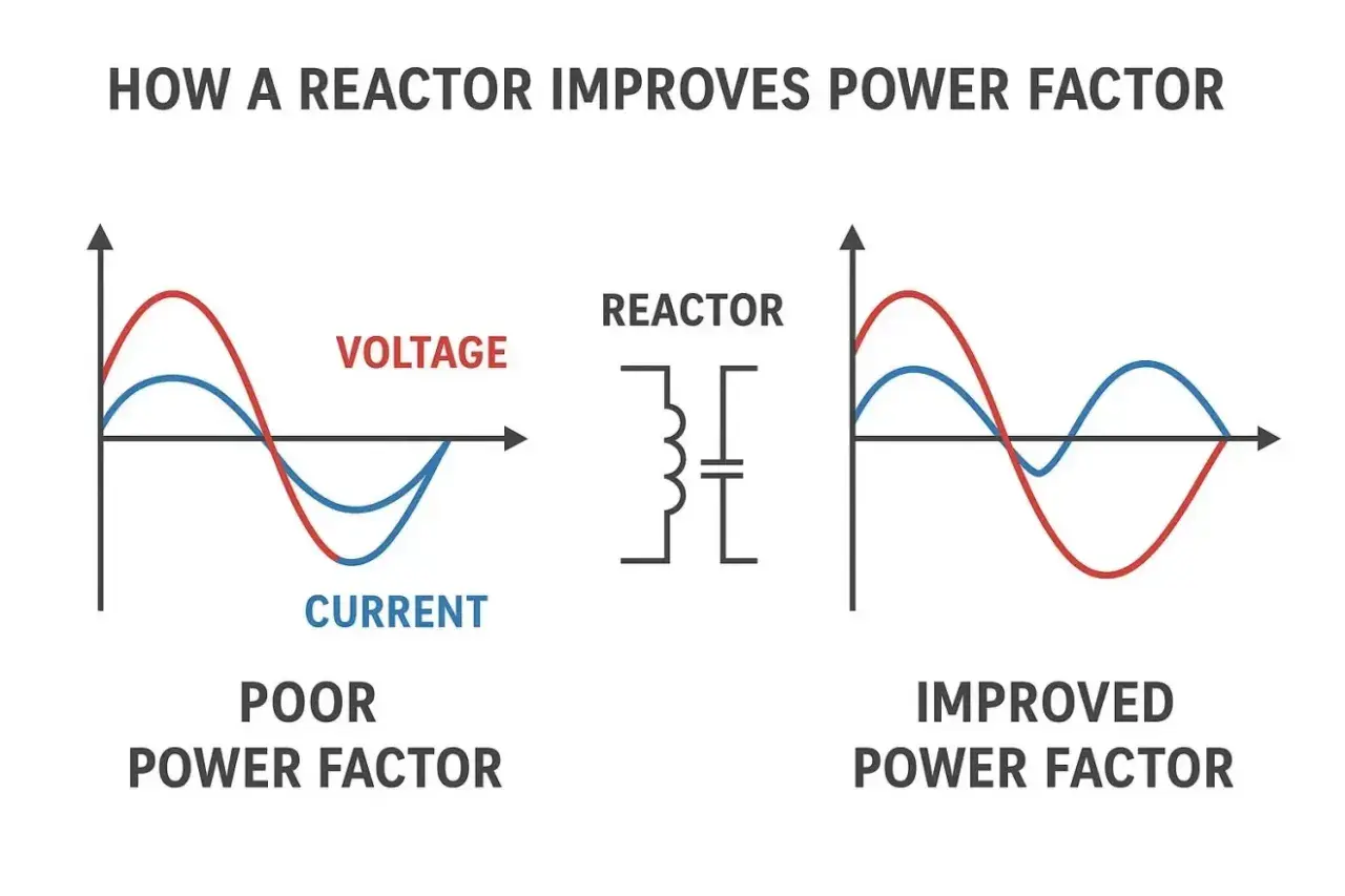
A drive does not send a smooth sine wave to the motor. It uses fast PWM switching from IGBTs, which are insulated gate bipolar transistors, to create a stepped waveform that approximates AC. An output reactor simply adds inductance in series with that path, which slows the rate of current change and takes the edge off the voltage rise.
That matters because the cable between the drive and motor is not an invisible wire. It has capacitance, and fast edges charge that capacitance very quickly. The result can be higher peak voltage at the motor terminals, more stress on insulation, and occasional nuisance trips when the load changes abruptly. Rockwell Automation describes this as a way to reduce dv/dt and motor-terminal peak voltage, while also helping the drive survive surge currents caused by rapid load changes.
I treat the reactor as a controlled form of electrical inertia. It is not there to make a machine "more powerful"; it is there to make the drive and motor behave more predictably when the cable, switching speed, and motion profile are working against each other. Once that is clear, the real question becomes when the machine actually needs it.
When I would add one to a motion-control system
ABB’s newer guidance is useful here because it avoids pretending there is one universal rule. There isn’t. In practice, I start looking seriously at output-side inductance when I see any of the following:
- The motor is physically far from the cabinet, especially on gantries, conveyors, cranes, or large packaging lines.
- The machine uses long retrofit cable runs that were never designed around a fast PWM drive.
- Several motors share one inverter and the combined load looks electrically light or awkward to the drive.
- The motor is low in leakage inductance, which means it does not naturally smooth current ripple very well.
- The system is running hotter, noisier, or less reliably after a carrier-frequency change.
- The drive trips on overvoltage or current spikes even though the mechanical load looks normal.
One detail people miss is that the symptom often looks mechanical when the root cause is electrical. A motor that is buzzing, heating up, or tripping at the edge of its speed range may not need a control rewrite at all; it may simply need the waveform cleaned up. That said, I would not use a reactor to hide a bad acceleration profile or a poorly tuned servo loop. If the axis is being shocked mechanically, the motion settings, braking strategy, or load inertia need attention first. From there, the next step is choosing the right size, not just adding any choke that fits the panel.
How I would size and rate the component
For most motion systems, the safest starting point is still modest impedance, usually around 3%. That gives you damping without stealing too much voltage from the motor. A 5% unit is the more aggressive option, but I would only choose it when the drive manual or the application risk really justifies the extra drop. On voltage-limited axes, too much inductance can eat into top-speed headroom, and that trade-off matters more in servo work than in a simple pump or fan.
Here is the checklist I use before I ever look at a part number:
| What I check | Why it matters | What I want to see |
|---|---|---|
| Drive current | The reactor must carry the full continuous load without overheating | Continuous current rating at least equal to the drive output current |
| Impedance | More impedance gives more damping, but also more voltage drop | Usually 3% to start, 5% only when clearly needed |
| Voltage class | 400 V, 480 V, and 690 V systems are not interchangeable | A part rated for the actual UK installation voltage |
| Thermal margin | Reactors are lossy components and need breathing room | Enough enclosure ventilation and spacing for continuous duty |
| Cable length | Longer drive-to-motor runs increase capacitance and stress | Short, well-routed motor-side cable where practical |
For really long cable runs, I stop thinking in terms of a plain reactor and start thinking in terms of total output protection. ABB’s 2024 note treats load reactors as the simplest and lowest-cost output filter, but also makes the important point that they are best for shorter distances. In the same family of solutions, a dV/dt filter is usually the cleaner answer when the cable run is stretching out, and sine-wave filters become relevant for very long distances, roughly the 300 m class and beyond. That distinction is the difference between a cheap fix and a durable one.
How it compares with dV/dt and sine-wave filtering
I rarely choose protection hardware in isolation. I compare the reactor against the two obvious alternatives: a dV/dt filter and a sine-wave filter. Each solves the same basic problem, but at a different level of completeness.
| Option | Best at | Trade-off | My rule of thumb |
|---|---|---|---|
| Load reactor | Simple damping, smaller voltage spikes, low-cost retrofits | Limited wave-shaping and some voltage drop | Use it first for moderate cable lengths and straightforward motion systems |
| dV/dt filter | Much better reduction of voltage rise rate and motor terminal stress | More space and cost than a plain reactor | Use it when the cable run is getting long or the motor insulation is a concern |
| Sine-wave filter | The cleanest motor waveform and the lowest electrical stress | Highest cost and largest footprint | Use it for very long runs or highly sensitive motors and bearings |
There is one more reason I do not treat the reactor as a universal answer: resonance. On some layouts, the added inductance can interact with cable capacitance and produce worse ringing instead of better behaviour. That is why a plain reactor is fine for many moderate applications, but not something I would drop into every drive cabinet by default. If the machine is sensitive, the better device is often the one that shapes the waveform more explicitly, even if it costs more. Once the protection choice is clear, installation quality decides whether the benefit survives contact with the real cabinet.
Installation choices that decide whether it works
The most common mistake is to fix the electronics on paper and then destroy the benefit in the cabinet. I want the reactor as close to the drive output as practical, with the motor-side cable kept short and routed cleanly. If the output cable runs through the same tray as control wiring, I expect trouble. If the cable shielding and earth bonding are sloppy, I expect trouble. If the reactor is bolted into a hot corner with no airflow, I expect trouble.
These are the practical checks I make before commissioning:
- Keep the reactor-to-drive lead short so the added inductance is actually working where intended.
- Use shielded motor cable and terminate the shield correctly at both ends where the drive design requires it.
- Separate power and control runs so the high-frequency switching noise does not leak into encoder or feedback wiring.
- Confirm that the reactor is mounted with enough clearance to shed heat continuously.
- Check the manufacturer’s wiring guidance for multi-motor or long-lead layouts before assuming the standard setup will hold.
With motion systems, clean installation is not a cosmetic issue. It directly affects feedback stability, EMC behaviour, and bearing life. Once those physical details are controlled, the country-specific and plant-specific questions become easier to answer.
What changes in a UK motion-control cabinet
In the UK, I usually meet 400 V, 50 Hz systems, often inside compact enclosures where every millimetre of cable routing matters. That makes the decision a little more practical than theoretical. A reactor has to fit the cabinet, preserve enough voltage margin for the motor at speed, and still leave room for sensible EMC practice. If the cabinet is being retrofitted into older European machinery, I also check whether the motor insulation and cable set were ever intended for modern PWM drive duty. That detail is often the hidden weak point.
For UK projects, I also pay attention to maintainability. If the part is hard to inspect, hard to cool, or hard to replace during a planned outage, it is not a good long-term choice even if the electrical numbers look fine on day one. Motion-control systems are unforgiving in that way: the electrical fix must also be operationally sensible. That is why I end every project with a short sign-off checklist instead of a vague feeling that the issue has been handled.
The checklist I would use before signing off a motion axis
If I had to reduce the decision to a few lines, this is the order I would follow before ordering anything:
- Confirm the drive voltage class, continuous output current, and overload duty.
- Measure the actual drive-to-motor cable length, not the optimistic one from the drawing.
- Check the motor insulation rating and whether it is inverter-duty ready.
- Decide whether the problem is simple surge damping or full waveform cleanup.
- Verify that the chosen part will not starve a high-speed axis of voltage margin.
- Review cable routing, shield terminations, and cabinet temperature before commissioning.
When the goal is simply to calm a fast inverter over a moderate cable run, a properly rated reactor is often the cheapest credible fix. When the cable is long, the motor is sensitive, or the machine is already living close to its speed limit, I move up to dV/dt or sine-wave filtering instead. That is the distinction that keeps a motion system reliable instead of merely functional.