In motion control, a small naming mistake can lead to the wrong part being ordered, the wrong fault being diagnosed, or the wrong torque margin being assumed. The rotor vs motor distinction sounds basic, but in real projects it decides whether you are talking about a single rotating assembly inside an electric machine or the complete device that produces motion. I focus here on the practical difference, how the parts work together, and what that means when you are selecting, sizing, or troubleshooting drive systems.
The short version is simple: a rotor is one part of the motor, and the motor is the whole machine
- The rotor is the rotating element inside the machine; the motor also includes the stator, housing, bearings, and often feedback hardware.
- In motion control, rotor inertia, balance, and magnetic design affect acceleration, smoothness, and heat.
- A motor selection decision should be based on load, duty cycle, torque-speed curve, and feedback needs, not rotor shape alone.
- Confusion usually appears when people compare a component spec with a whole-machine rating.
- Servo systems work best when the motor, drive, encoder, and gearbox are sized as one axis, not as isolated parts.
What the rotor actually is
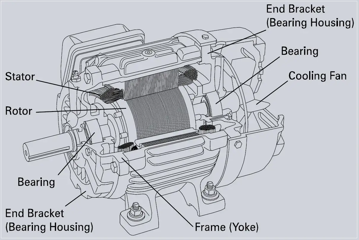
I use the simplest accurate model first: the rotor is the rotating internal part of an electric machine, while the stator is the stationary part around it. ABB’s motor guide describes the stator as the stationary element surrounding the rotor, which is the cleanest way to picture the relationship without overcomplicating it.
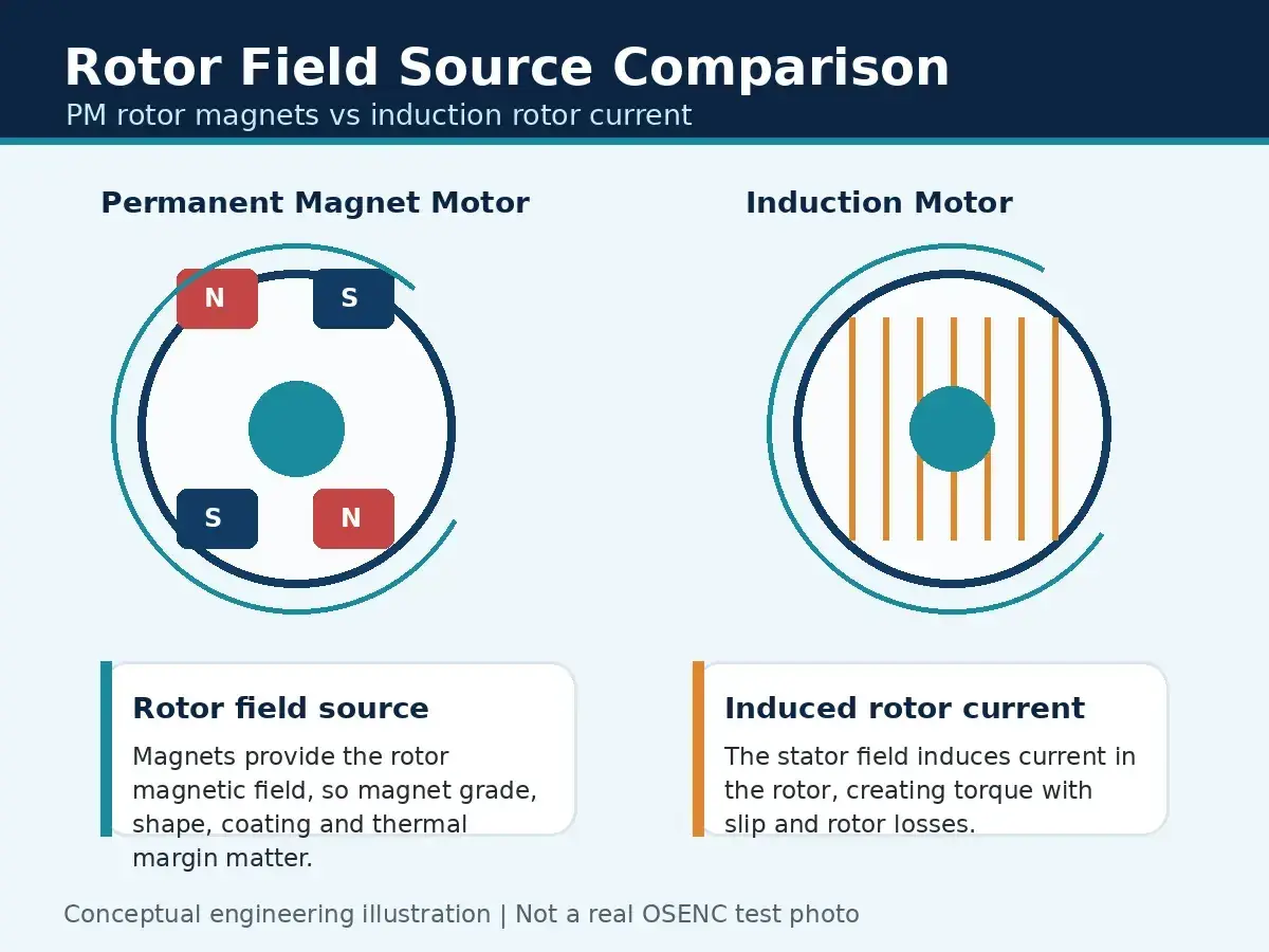
What sits on the rotor depends on the machine type. In an induction motor, the rotor may be a squirrel-cage structure with conductive bars; in a permanent-magnet motor, it carries magnets; in a wound-rotor design, it carries windings. The shaft is often attached to the rotor, but the shaft itself is not the rotor.
- Rotor means the rotating electromagnetic assembly.
- Shaft means the mechanical output member that transmits torque.
- Stator means the fixed part that creates the magnetic field or receives the windings.
- Bearings support the rotating parts but are not part of the rotor.
That distinction matters because a rotor can be repaired, balanced, or replaced as a component, while the motor is the assembled machine you actually mount and control. From here, the more useful question is how that component compares with the full machine in practice.
How the component and the whole machine compare in practice
When people use these terms loosely, they usually blur two different levels of thinking: part-level design and system-level performance. Siemens’ test-stand material treats the stator and rotor as produced parts that still need function testing before the motor is complete, which is exactly how I think about the difference in a production or commissioning environment.
| Aspect | Rotor | Motor |
|---|---|---|
| Scope | The rotating electromagnetic assembly | The complete electric machine |
| Main job | Convert magnetic interaction into rotation | Convert electrical input into usable mechanical output |
| Typical contents | Magnets, bars, windings, laminated core, shaft interface | Rotor, stator, housing, bearings, terminals, cooling, often feedback hardware |
| Key specs | Inertia, balance, magnetic layout, rotor losses | Torque, speed, efficiency, duty cycle, thermal limit |
| Failure clues | Imbalance, demagnetisation, broken bars, rotor winding faults | Overheating, poor commutation, bearing wear, insulation failure |
That table is the practical answer to the comparison: you can evaluate a rotor, but you cannot treat it as a finished actuator. A motor gives you the whole performance envelope, while the rotor is only one piece of that envelope.
Why the distinction matters in motion control
In motion control, I care less about terminology for its own sake and more about what it changes in the axis. A rotor’s inertia, balance, and magnetic design affect how fast the system accelerates, how cleanly it settles, and how much vibration shows up at the load.
- Acceleration and stopping depend heavily on inertia. A heavier rotor can make an axis feel sluggish unless the drive and load are matched properly.
- Torque ripple shows up as speed variation, especially at low speed. That is where rotor geometry and commutation quality matter more than a simple watt rating.
- Thermal behaviour is not just about the windings. Rotor losses, magnet temperature, and airflow can become limiting factors in compact or high-speed axes.
- Feedback accuracy depends on the whole motor shaft path, not on the rotor alone. Encoder mounting and shaft runout can make a good motor behave poorly.
- Load matching is a system problem. If the reflected inertia is badly mismatched, the controller spends energy correcting the error instead of moving the load cleanly.
For a servo axis, I usually think in terms of the complete loop: motor, drive, encoder or resolver, gearbox if there is one, and the load. Once that loop is clear, it becomes easier to interpret rotor design choices without confusing them with the behaviour of the finished axis.
Rotor designs you will meet in real equipment
The rotor is not one fixed design. Different machines use different rotor constructions, and those differences affect cost, ruggedness, maintenance, and motion quality. If you are comparing platforms, this is where the technical trade-offs start to show.
Squirrel-cage rotors
These are common in induction motors because they are robust, simple, and low maintenance. I usually associate them with pumps, conveyors, fans, and other applications where ruggedness matters more than extremely fine dynamic response.
Wound rotors
Wound-rotor machines are less common in modern compact motion systems, but they still matter in applications that need specific starting or control characteristics. They are worth understanding because their construction is different enough that fault handling and maintenance are not the same as for a cage rotor.
Permanent-magnet rotors
These dominate many servo and precision motion-control systems because they offer strong torque density and good controllability. In practice, they help when you need clean low-speed behaviour, compact packaging, and fast response.
Read Also: Overload Relays - Avoid Costly Motor Failures. Learn How.
Low-inertia and ironless rotors
These are used when smoothness and rapid acceleration are more important than brute force. They are valuable in pick-and-place, laboratory automation, and other axes where cogging and overshoot can ruin precision, but they are also more application-specific and often more expensive.
Once you know the rotor type, the next step is not just choosing a bigger motor. It is specifying the right axis in a way that respects the load, feedback, and control strategy.
How to specify the right part on a project
When I size a motion axis, I try to avoid beginning with the motor nameplate. I start with the motion profile, because that tells me whether the real challenge is peak torque, continuous torque, speed, settling time, or thermal headroom.
- Define the load profile, including mass, friction, speed, acceleration, and dwell time.
- Check whether you need rotor-level data, full motor data, or a complete motor-drive package.
- Compare continuous torque, peak torque, and inertia instead of looking only at power.
- Verify feedback requirements early, especially if the application needs precise homing or repeatable positioning.
- Confirm the mechanical interface, including shaft size, mounting pattern, brake, and gearbox if used.
- Validate thermal limits under the actual duty cycle, not just in free-air catalogue conditions.
A 10:1 gearbox, for example, multiplies torque at the load by roughly ten while reducing speed by roughly the same factor, so it can completely change how the motor and rotor behave in the real machine. That is why the finished axis has to be sized as a system, not as a collection of isolated parts.
Where confusion usually causes the most trouble
The mistakes I see most often are not dramatic; they are just expensive. They start with language, then turn into poor part selection, then show up later as noise, heat, missed position, or premature wear.
- Ordering a rotor when the actual fault is in the stator winding or the bearings.
- Comparing a bare rotor specification with a full motor rating and assuming they mean the same thing.
- Assuming higher speed automatically means better motion performance.
- Ignoring the drive and encoder, then blaming the motor for poor settling time.
- Forgetting that cooling, housing stiffness, and shaft alignment are part of the machine, not the rotor.
The pattern is predictable: if you treat the rotor as the whole machine, you under-specify the axis; if you treat the whole motor as just a spinning part, you miss the details that decide whether the application is stable. That is why I always separate component-level diagnosis from system-level sizing.
What I would check before I sign off a motion axis
If I were reviewing a design for a production line, packaging cell, or compact automation module, I would keep the checklist short and practical. I would want to know whether the rotor design supports the motion profile, whether the full motor can shed heat under real duty, and whether the control loop has enough feedback quality to settle cleanly.
- Is the rotor inertia compatible with the required acceleration and stop time?
- Does the motor deliver enough continuous torque at the actual operating speed?
- Is the feedback device accurate enough for the positioning tolerance?
- Will the gearbox, if present, help the axis or simply add friction and backlash?
- Can the thermal path handle the duty cycle without drift or derating?
That is the practical way I separate the two terms: the rotor tells me about one rotating part of the machine, while the motor tells me whether the whole assembly can do the job reliably. If you keep that split clear, the specifications become easier to read, the selection process becomes faster, and the motion axis is much less likely to surprise you later.