A high speed stepper motor is useful when a machine needs fast indexing, repeatable positioning and a compact control package without jumping straight to a servo axis. The hard part is that speed is not decided by the motor label alone; the driver, supply voltage, winding style and load profile decide whether the axis stays stable or falls off its torque curve. In this article I focus on what really raises usable speed, where the technology fits best, and how to choose it without overpaying for performance you will never use.
The points that matter before you size the axis
- Speed is a system property. A motor, driver and supply that look fine separately can still miss torque at speed.
- The speed-torque curve is the real map. Static holding torque tells you little about how the axis behaves during acceleration.
- Low inductance and enough bus voltage matter more than microstepping. Microstepping smooths motion, but it does not create missing torque.
- Closed-loop stepper systems sit between open-loop steppers and servos. They are often the sensible middle ground when missed steps are expensive.
- UK machine builds need the same discipline as any other market. Supply, EMC, thermal and support decisions should be settled before the panel is built.
What actually makes a stepper fast
In practice, I treat speed as a current-delivery problem. A stepper has to build phase current quickly enough to keep the rotor locked to the commanded pulses, and coil inductance is what resists that current rise. That is why two motors with the same frame size can behave very differently once you push them past the easy part of the curve.
This is also why the same motor can look excellent with one drive and disappointing with another. Oriental Motor’s guidance makes this point clearly: the speed-torque curve is specific to a motor and driver combination, not just the motor itself. If you want usable high speed, look for a low-inductance winding, a drive with enough voltage headroom and a load profile that does not demand brutal acceleration.
A typical 1.8° hybrid stepper gives 200 full steps per revolution, and 8x or 16x microstepping is common for smoother motion. The catch is that finer microstepping does not increase the motor’s fundamental torque limit; it only makes the motion quieter and less granular. For two-phase motors, bipolar-parallel wiring is often favoured for high-speed work because the effective inductance is lower and the torque holds out longer.
That is the point where pull-in torque and pull-out torque start to matter. Pull-in torque is what the axis can start from standstill, while pull-out torque is what it can hold once it is already moving. Once you understand that difference, the next question is not “How fast can it spin?” but “Where does it still stay on the curve?”
Where it earns its place on the line
These motors make sense when the machine spends most of its life moving between positions rather than cruising continuously. I see them in index tables, pick-and-place heads, scanners, lab instruments, light packaging stations, feeders and small automation axes where repeatability matters more than absolute top-end speed.
They are less convincing on long, variable-duty moves with heavy reflected inertia or load torque that swings hard during the cycle. If the application needs fast continuous running, wide speed range and strong efficiency at the top end, a servo often earns its price more quickly than a stepper that is being pushed beyond its comfort zone.
- Good fit when the move is short, repeatable and the load is predictable.
- Good fit when holding position at stop matters more than continuous high rpm.
- Poor fit when the load changes a lot or the axis must sprint hard for long periods.
In short, I use steppers for fast positioning, not for pretending that every motion axis is a miniature servo. From there, the real work is choosing the motor, driver and supply as a single system.
How I choose the motor, driver and supply as one system
I start with the motion profile, not the catalogue. Distance, target speed, acceleration, deceleration, cycle time and duty cycle all matter, because the motor has to survive the whole move, not just the headline rpm.
| Factor | What I check | Why it matters |
|---|---|---|
| Torque at speed | The available torque at the real running speed, not the static holding figure | If the required curve crosses the available curve, the axis stalls or loses position |
| Inductance | Lower inductance where high speed is the priority | Current rises faster, so torque survives further up the speed range |
| Driver voltage | Enough bus voltage for the chosen winding and load profile | More voltage helps the phase current reach target faster |
| Winding connection | Bipolar-parallel if the motor family offers it | It usually gives better high-speed performance because inductance is lower |
| Inertia ratio | Reflected load inertia versus rotor inertia | An extreme ratio makes acceleration harder and increases the risk of resonance |
| Thermal headroom | Motor temperature and drive current after a full duty cycle | A motor that is technically inside spec can still become unreliable if it runs too hot |
I usually leave a real safety margin rather than designing right on the edge. AutomationDirect’s drive manuals make the practical warning plain: at speed, coil current can be lower than the set value because inductance limits how quickly the current rises. That is why a drive setting that looks correct on paper may still underdeliver once the axis starts moving.
That selection process is where many projects either become robust or become expensive to debug. Once that architecture is set, the remaining question is whether an open-loop, closed-loop or servo axis fits best.
Open loop, closed loop or servo
This is the comparison I use when a project is near the decision point. The cheapest option is not always the cheapest after the first missed move.
| Option | What it does well | Trade-off | Best fit |
|---|---|---|---|
| Open-loop stepper | Low cost, simple wiring and strong holding behaviour at stop | It can miss steps if the load or acceleration is too aggressive | Short, predictable moves with modest torque demand |
| Closed-loop stepper | Encoder feedback, better stall protection and more confidence under changing load | Higher cost and a little more system complexity | Production axes where missed steps are unacceptable but full servo complexity feels excessive |
| Servo | Best speed range, strong dynamic response and broad tuning capability | Highest complexity and usually the highest cost | Heavy loads, longer moves and applications that live near the top of the speed envelope |
Why high-speed projects fail on the bench
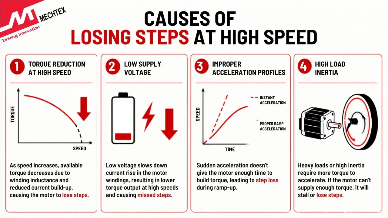
When a prototype misses position or stalls early, the cause is usually more ordinary than people expect. The most common mistake is sizing from holding torque instead of the torque available at speed. A stepper can look impressive at standstill and then run out of usable torque much sooner than the drawing suggested.
- Too little supply voltage. The current does not rise fast enough, so the motor loses torque as speed climbs.
- Too much inductance. A winding that looks strong at low speed can be weak where the move actually happens.
- Acceleration that is too abrupt. Some motors have a maximum starting speed around 1000 pulses per second, so the first burst can fail even if cruising speed is fine.
- Ignoring resonance. The motor and mechanics can amplify vibration in a narrow band and trigger stalls.
- Expecting microstepping to solve everything. It smooths motion, but it does not create torque.
- Mechanical drag. Misalignment, belt tension, sticky bearings and poor cable routing can eat the margin you thought you had.
Oriental Motor’s notes on stepper behaviour are consistent with what I see in the field: the curve matters more than the label, and the start profile matters more than people think. When the bench test fails, I rarely find a mysterious motor defect; I usually find a bad assumption about load, current or acceleration.
That is why the fix is often not a new motor at all. More often, it is a better drive, a cleaner profile or a small mechanical change that lets the existing axis breathe.
How to squeeze more speed without a full redesign
If the first prototype is close but not quite there, I do not jump straight to a different motor family. I usually try the least disruptive changes first, because they often deliver the best return for the least engineering time.
- Raise the bus voltage within the driver’s rating so the current can rise quickly enough at speed.
- Choose a lower-inductance winding or bipolar-parallel connection if the motor family supports it.
- Use a smoother acceleration profile so the axis moves through the awkward speed band without dwelling there.
- Reduce reflected inertia with a pulley change, a lighter payload or a modest gearbox if torque matters more than output rpm.
- Improve alignment and friction before blaming the electrical side.
- Move to feedback if losing steps would damage product or stop the line.
I treat microstepping as a motion-quality tool, not a speed upgrade. It helps with smoothness and acoustic behaviour, but it will not rescue a torque budget that is already too tight. If you need both speed and stiffness, reducing mechanical stress or adding feedback usually pays off faster than chasing one more microstep setting.
Once those fixes are not enough, it is time to look at the broader machine context, including the panel, the supply architecture and the market the machine is being built for.
What I would check first on a UK machine build
For a UK panel, I would check the power architecture early. If the drive wants DC bus power, the PSU, fuse protection and cabinet heat load need to be designed around that; if it takes mains input, the panel layout and thermal margin change again. Those details are boring only until a machine arrives on site and starts running hot.
- Power matching between the supply, drive and motor, rather than assuming the cabinet can absorb every configuration.
- EMC and grounding so the axis remains stable beside contactors, sensors and networked controllers.
- Thermal headroom in a sealed enclosure, especially when the machine runs all day.
- Spare parts and lead times because availability matters more than a glossy catalogue page when production is down.
- Status and diagnostics if the machine is part of a smart manufacturing or IoT environment.
In real industrial automation, the motion axis is never isolated from the cabinet around it. The cleaner the electrical and mechanical environment, the more honestly the motor can show its actual performance. That broader view is what keeps the prototype from becoming a one-off success.
The decision that saves the next redesign
If I had to reduce the decision to one rule, it would be this: choose the motor that stays comfortably on its speed-torque curve at the real load speed, not the one that looks best at standstill. That usually means low inductance, the right driver voltage, a realistic acceleration profile and enough mechanical margin to absorb variation in the product or fixture.
For most motion-control projects, that disciplined first prototype saves more time than any later tweak. It also makes the next decision easier, because you will know whether the problem was the motor, the drive or the machine around it.