The device buys time for overloads and reacts instantly to short circuits
- Thermal action handles sustained overloads, so normal start-up surges do not automatically trip the circuit.
- Magnetic action reacts in milliseconds when a short circuit appears.
- In the UK, the right choice depends on the installation standard, the cable, the fault level, and the load profile, not just the amp rating.
- B, C, and D curves are the practical shorthand most engineers use for final circuits and many industrial loads.
- For motors, a dedicated motor protection breaker is often a better fit than a general-purpose device.
What it is and why it matters in a real panel
I think of this device as a compromise done properly. It is built to protect conductors and equipment from two very different problems: the slow, cumulative heating of an overload, and the violent energy spike of a short circuit. That makes it useful anywhere a circuit needs both tolerance for routine load variation and a firm response when something actually goes wrong.
In practice, the thermal side protects against damage that builds up over time, while the magnetic side prevents a fault from turning into burnt insulation, welded contacts, or a damaged drive or contactor. The same principle shows up in smaller control panels, distribution boards, machine cabinets, and motor feeders, but the exact device style changes with the application. A final-circuit MCB, a feeder MCCB, and a motor protection breaker can all use the same basic idea without being interchangeable.
The real value is not the nameplate. It is the behaviour under stress. A good protection device lets a machine ride through normal inrush, then clears the fault fast enough to preserve the panel, the cable, and the downtime budget. That is why the trip curve matters so much, and it leads directly to the next question, which is how the two tripping elements actually work.
How the thermal and magnetic elements split the job
The thermal element is the slow one. It usually relies on a bimetal strip, which bends as it heats up when current stays above the normal operating level. That delay is intentional: it gives motors, transformers, lighting circuits, and power supplies room to start without nuisance tripping. The magnetic element is the fast one. It uses a solenoid or similar electromagnetic release to trip almost immediately when current rises sharply, as it does during a short circuit.That split is the whole point. Overloads need a measured response because heat accumulates gradually. Short circuits need a near-instant response because fault current can destroy equipment in milliseconds. In practical terms, overload protection is measured in seconds to minutes, while short-circuit clearing happens in milliseconds.
| Fault condition | What the breaker does | Typical response | Why it matters |
|---|---|---|---|
| Moderate overload | Thermal element heats and bends until it trips | Seconds to several minutes | Protects cables and equipment from cumulative heating |
| Normal start-up surge | Usually rides through if the surge stays inside the curve | Brief, non-tripping window | Prevents nuisance trips on motors and inductive loads |
| Short circuit | Magnetic element trips the mechanism almost instantly | Milliseconds | Limits arc energy and reduces the chance of major damage |
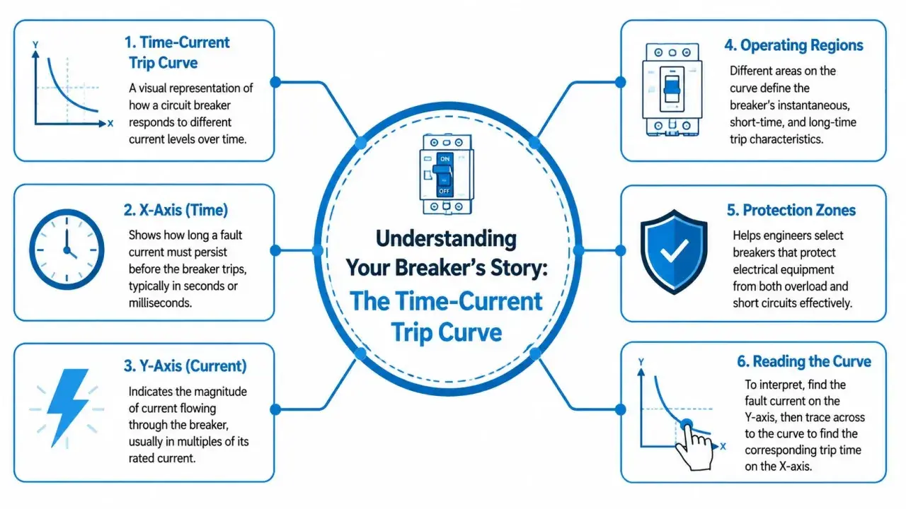
The curve printed on the device or in the data sheet is really a map of those two responses. Once you can read it, a lot of otherwise confusing specification work becomes much clearer. The next step is to place that behaviour in the UK standards and equipment landscape.
Where it fits in UK electrical systems
In the UK, the device family you choose depends on the job in front of you. For many final circuits, a miniature circuit breaker to BS EN 60898 is the familiar choice. For industrial or similar applications, BS EN 60947-2 becomes more relevant, especially when you are dealing with larger currents, higher breaking capacities, or adjustable settings. That distinction matters because the same basic protection principle is used in different ways across the system.
Here is the practical view I would use on site or in a panel design review.
| Application | Typical device style | Why it fits |
|---|---|---|
| Lighting, socket circuits, smaller final circuits | MCB with B, C, or D characteristics | Compact, fixed protection, easy to standardise |
| Distribution feeders and larger outgoing ways | MCCB | Higher current ratings, higher breaking capacity, often adjustable |
| Main incomer or large low-voltage board | ACB | Very high current capacity and stronger selectivity options |
| Motor branches | Motor protection breaker or starter protector | Combines overload and short-circuit protection in one compact device |
For UK installations, the point is not only whether the breaker can carry the load. It also has to satisfy disconnection requirements, earth fault loop impedance expectations, and the prospective fault level at the point of installation. A breaker that looks right on paper can still be the wrong device if the system cannot guarantee safe automatic disconnection. That is why the curve selection itself deserves its own section.
How I choose the right trip curve
The common B, C, and D curves are just shorthand for how much instantaneous current the breaker will tolerate before the magnetic part trips. In simple terms, B is the most sensitive, C is the middle ground, and D is the most tolerant of inrush. The typical ranges are 3 to 5 times In for B, 5 to 10 times In for C, and 10 to 20 times In for D.
- B curve works well for resistive loads, standard socket circuits, and circuits with little inrush.
- C curve is the usual choice for inductive motors, mixed loads, general lighting, and many control circuits.
- D curve suits transformers, high-inrush motors, discharge lighting, and other loads with a large start-up spike.
The mistake I see most often is someone using a higher curve to stop nuisance trips and then forgetting to check the impact on disconnection time and earth fault loop impedance. That can solve the symptom while creating a compliance problem. A C curve might be perfect for a motor feeder, but if the circuit is long, the impedance is high, or the fault level is borderline, the same choice may no longer be acceptable.
I also treat ambient temperature as a real variable, not an afterthought. Thermal protection responds to heat, so enclosure conditions, ventilation, and group loading all matter. If the panel runs hot, the effective margin shrinks. If the load has significant harmonics or a non-standard start profile, I want to see the manufacturer’s time-current data before I sign off the choice. That is exactly where a motor-specific device often becomes more sensible than a generic breaker.
When a motor protection breaker is the better tool
For motors, I usually prefer a dedicated motor protection breaker or starter protector when the circuit is more than a simple final feeder. Motors bring starting current, thermal inertia, and sometimes phase-loss sensitivity into the picture. A device made for that job can combine thermal overload protection and magnetic short-circuit protection in one compact unit, which simplifies the panel and reduces the number of separate parts you have to coordinate.
This is especially useful on pumps, fans, conveyors, compressors, and smaller machine tools. In those applications, the breaker is not just protecting a cable. It is helping the machine start cleanly, survive a jam, and stay serviceable without unnecessary rewiring. Some motor-protection devices also add manual switching or phase-loss detection, which is useful when uptime and fault diagnostics matter more than absolute simplicity.
- Choose a motor protection breaker when the load is a motor and the starting behaviour is part of the design.
- Use a generic thermal-magnetic breaker when you need straightforward overload and short-circuit protection for a standard branch circuit.
- Move to a contactor plus overload relay when the motor is larger, the coordination need is tighter, or the control logic is more complex.
- Consider an electronic trip solution when diagnostics, selectivity, or remote monitoring matter more than lower upfront cost.
That last point matters in modern industrial automation. Once the panel starts carrying drives, PLCs, communication modules, and remote signalling, protection stops being only about interruption and becomes part of the system’s observability. That is where the comparison with fuses and electronic trip units becomes useful.
Thermal-magnetic, fuse, or electronic trip unit
There is no single winner here. Each option solves the same safety problem in a different way, and the right answer depends on cost, fault level, maintenance access, and how much coordination you need upstream and downstream. I would not choose a thermal-magnetic breaker simply because it is familiar; I would choose it because it is the best match for the actual circuit.
| Option | Strengths | Trade-offs | Best fit |
|---|---|---|---|
| Thermal-magnetic breaker | Resettable, compact, familiar, good general-purpose protection | Less adjustable than electronic trip units | Final circuits, many industrial branches, moderate complexity |
| Fuse | Very simple, strong current-limiting behaviour, often low cost | Single-use, replacement downtime, less convenient for maintenance | High fault levels, compact protection, straightforward coordination |
| Electronic trip unit | More precise settings, better selectivity, easier to integrate with monitoring | Higher cost and configuration effort | Critical feeders, richer diagnostics, panels with uptime priorities |
If I need a protection device to do one job reliably and stay out of the way, the thermal-magnetic route is often enough. If I need data, remote signalling, tighter selectivity, or more tuning headroom, I start looking at electronic trip units earlier. If I need strong fault limitation in a simple form factor, a fuse can still be the best answer. The final decision comes down to the checks I would make before approving the design.
What I check before I sign off the protection
Before I approve a breaker for a panel, I run through the same practical questions every time. They are simple, but they prevent most avoidable mistakes.
- Does the breaking capacity exceed the prospective fault current at the point of installation?
- Does the curve match the load profile, including start-up current and duty cycle?
- Will the circuit still meet disconnection requirements with the chosen curve and cable length?
- Has the ambient temperature and enclosure ventilation been accounted for?
- Is the device coordinated with upstream protection and any downstream starters or drives?
- For motors, transformers, and VFDs, does the manufacturer give specific guidance that overrides a generic rule of thumb?
When those checks line up, the protection behaves the way engineers expect it to behave: tolerant when the load is healthy, decisive when the fault is real, and predictable when maintenance time is tight. That is the standard I use, because in electrical systems the best breaker is not the one with the biggest number on the label, but the one that fits the circuit without compromise.