Arc quenching is the controlled extinction of an electrical arc after contacts open, and the details matter because the wrong interruption method can leave you with damaged gear, unnecessary downtime, or a much bigger safety problem than the fault itself. In practice, I think of it as a race between the arc losing energy and the system trying to re-establish voltage across the gap. That race is won differently in low-voltage boards, medium-voltage switchgear, and DC installations.
What matters most in practice
- An arc survives because the ionised path stays conductive even after the contacts separate.
- In AC systems, successful interruption depends on the current zero and on how fast dielectric strength recovers.
- Vacuum interrupters now dominate many medium-voltage applications because they recover quickly and stay compact.
- Gas, oil, air, magnetic blow-out, and semiconductor-based methods still matter in the right duty range.
- DC circuits need a different strategy because they do not get a natural current zero.
- In the UK, the best designs usually align with IEC-based BS EN standards and a realistic maintenance plan.
What keeps an electrical arc alive after contacts open
An arc is not just a spark that lingers for a moment. It is a hot, ionised column of gas or vapour that can keep conducting current even after the switch contacts start moving apart. The heat is so intense that the surrounding material can contribute more metal vapour to the plasma, which makes the arc easier to sustain and harder to remove.
The practical point is simple: once the contacts part, the fault is not over. The system must remove energy from the arc fast enough that the gap regains insulation strength before the voltage across it rises again. In AC equipment, that usually means surviving the current zero; in DC equipment, there is no such gift, which is why the interruption problem becomes much tougher. That difference is the reason I separate the physics from the hardware before talking about the methods themselves.
How interruption really happens inside switchgear
A breaker does not usually “snuff out” an arc in one motion. It stretches, cools, and de-ionises it while the contact gap increases. At the same time, the insulation medium around the gap has to recover faster than the transient recovery voltage, or TRV, which is the voltage that appears immediately after current interruption. If dielectric strength comes back too slowly, the arc restrikes and the interruption fails.
That is why contact design matters so much. Shape, speed, stroke, and chamber geometry all influence how the plasma is split up and how quickly the gap becomes non-conductive again. Some devices use magnetic forces to drive the arc into splitter plates; others use vacuum or gas to reduce the ionised path itself. Once you understand that balance, the different interruption media start to make sense.
The main methods used to put out an electrical arc
There is no single “best” method for every electrical system. The right choice depends on voltage, fault level, switching duty, footprint, maintenance access, and whether the installation is AC or DC. Here is the practical comparison I use when I want to see the trade-offs clearly.
| Method | How it works | Best fit | Main limitation |
|---|---|---|---|
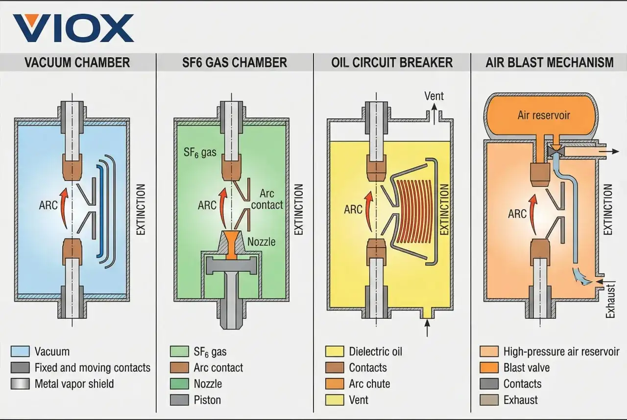
| Vacuum interrupter | The arc forms in a sealed vacuum, then collapses quickly as current reaches zero and dielectric strength recovers fast. | Most medium-voltage switchgear and many advanced breaker designs. | Needs the right type-tested interrupter and careful attention to recovery voltage. |
| Gas-insulated and SF6-based gear | The gas cools and de-ionises the arc while also providing insulation around live parts. | High-voltage GIS and compact substations. | Gas handling, leakage control, and environmental pressure make design and maintenance more demanding. |
| Oil interruption | The arc decomposes the oil, creating a cooling and de-ionising effect that helps extinguish it. | Older or legacy installations. | Fire risk, maintenance burden, and ageing insulation concerns. |
| Air blast and air-based interruption | Compressed air or shaped air paths lengthen and cool the arc. | Historical high-voltage gear and some special-duty applications. | Bulky equipment and more mechanical complexity. |
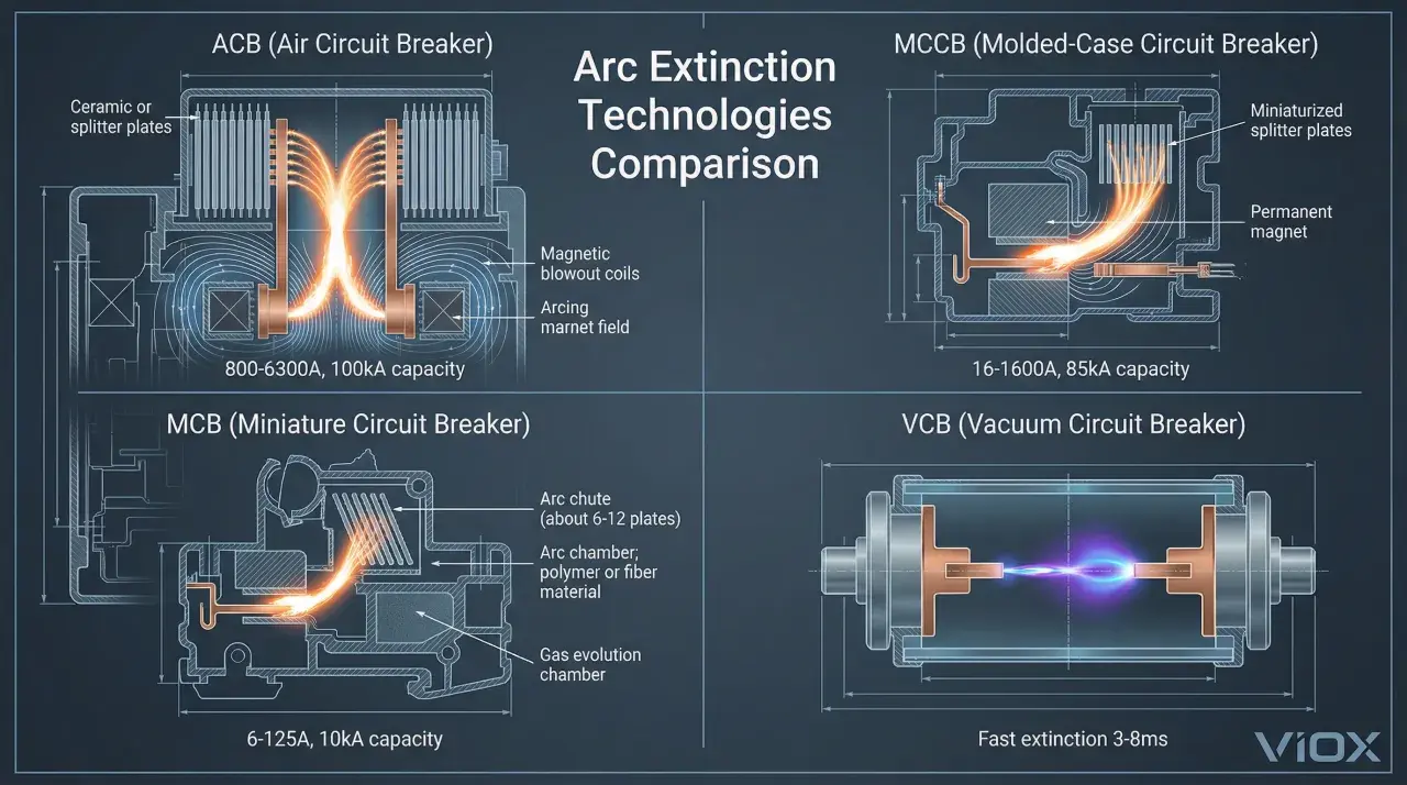
| Magnetic blow-out and arc chutes | Magnetic force pushes the arc into splitter plates, where it is lengthened and cooled. | Low-voltage breakers, contactors, and motor control gear. | Works best at lower energies and lower voltages. |
| Hybrid and semiconductor-based interruption | Electronics carry or commutate the current, then mechanical contacts open under reduced stress. | DC systems, fast arc mitigation, and specialised protection schemes. | Higher cost, heat management, and design complexity. |
In medium-voltage distribution, vacuum is often the most practical answer because the arc energy is low and the interrupter regains strength quickly. In high-voltage or very compact gas-insulated systems, the gas medium still has a role, although the industry is clearly pushing hard toward lower-impact alternatives. In low-voltage equipment, arc chutes, magnetic blow-out, and current-limiting designs remain valuable because they can cut fault duration before the energy becomes destructive. The real lesson is that the medium, the voltage class, and the switching duty have to be treated together, not as separate choices.
Why dc needs a different playbook
DC arc interruption is a different problem because the current does not naturally pass through zero fifty or sixty times a second. That means the arc can keep feeding itself unless the device forces current to collapse, diverts it, or transfers it into another path. In other words, you cannot rely on the AC zero crossing to do the hard work for you.
That is why battery energy storage systems, photovoltaic combiner gear, DC microgrids, traction equipment, and fast-charging infrastructure often use hybrid interrupters, semiconductor devices, or very carefully engineered mechanical contact systems. In those installations, a straightforward AC-style breaker approach is usually not enough. If I am reviewing a DC design, I look first at the interruption strategy, then at thermal behaviour, then at how the protection scheme handles a persistent fault. That order matters, because DC faults can escalate faster than people expect.
How I choose the right method for a plant or panel
When I narrow the options, I start with the duty rather than the catalogue. A method that looks elegant on paper can be the wrong answer if it cannot survive the fault level, the switching frequency, or the maintenance reality of the site. For a UK industrial project, I would usually check the following first.
| Selection factor | Why it changes the answer |
|---|---|
| Voltage class | Low-voltage, medium-voltage, and high-voltage systems use different interruption technologies for a reason. |
| Fault current | Higher fault levels need faster energy removal and stronger contact and chamber design. |
| AC or DC | DC often needs forced commutation or semiconductor help because there is no natural current zero. |
| Maintenance access | A highly compact device is not much use if you cannot inspect, test, or replace it safely. |
| Environmental constraints | Gas choice, leak management, and sustainability goals can rule out otherwise workable designs. |
| Arc-flash objectives | Clearing the arc and limiting incident energy are related, but they are not the same problem. |
One detail I always stress is that fast clearing is only part of the answer. A device may interrupt the fault quickly and still leave you with poor selectivity, unnecessary outages, or awkward maintenance intervals. Some modern vacuum interrupter designs are type-tested for many thousands of operations, and that matters in plants with frequent switching or heavy duty cycles. Once those constraints are clear, choosing between the available methods becomes much easier.
Mistakes that make protection look better on paper than in service
The mistakes I see most often are not exotic. They are usually design shortcuts. A team assumes the breaker alone will solve the problem, or they pick a technology because it is compact without checking whether the recovery voltage and duty cycle suit the chamber design. Another common error is treating arc suppression and arc-flash mitigation as the same thing, when in reality one is about extinguishing the fault and the other is about reducing the energy released while the fault exists.
- Choosing the medium before confirming the fault level and switching duty.
- Ignoring DC behaviour and assuming AC rules will translate cleanly.
- Overlooking contact wear, timing drift, or chamber ageing in high-cycle equipment.
- Mixing up interruption performance with personnel protection performance.
- Underestimating the importance of coordination with relays, fuses, and upstream devices.
There is also a subtle failure mode that shows up in retrofit projects: the original gear may have been adequate when installed, but the surrounding system has changed. More distributed generation, more battery storage, higher short-circuit contribution from certain sources, or altered operating modes can make an older interruption method look weak. The hardware did not suddenly become bad; the system around it changed, which is why review and testing matter. That shift matters because it changes both the equipment you buy and the maintenance model you live with.
Why UK switchgear is moving toward vacuum and clean air
In current UK projects, I increasingly see IEC-based BS EN standards shaping the spec, especially for low-voltage and medium-voltage gear. That is not just a paperwork issue. It pushes designers toward equipment with clear interruption ratings, documented test behaviour, and maintenance regimes that can be explained to operations teams rather than just to engineers.
The technology trend is just as clear. Vacuum interrupters are now a default choice in much medium-voltage equipment because they extinguish the arc quickly and keep the package compact. At the same time, many newer gas-insulated designs are moving toward clean-air or vacuum-based solutions instead of relying on SF6 alone. For industrial automation and smart manufacturing sites, that is a practical improvement: less environmental baggage, less complication around servicing, and a better fit for modular, digitally monitored plant.If I had to reduce the whole topic to one working rule, it would be this: pick the interruption method that matches the electrical duty first, then verify that it still makes sense for maintenance, compliance, and future expansion. That is how you end up with switchgear that clears faults reliably, protects people better, and stays usable long after the commissioning team has moved on.