The main lesson is that immunity is decided by the whole system, not one component
- The test checks how equipment behaves under transient overvoltage, including recovery, reset, and hidden damage.
- The lab standard defines a repeatable method, but it is not a direct lightning strike test or an insulation withstand test.
- In the UK, overvoltage protection is often a design requirement, not an optional extra.
- SPDs work best as coordinated layers, not as a single device chosen in isolation.
- The most useful report shows the setup, the operating mode, and the exact behaviour observed during stress.
What surge testing actually proves
In plain terms, a surge immunity test applies a controlled transient overvoltage to an equipment under test so you can see how it behaves under stress. IEC 61000-4-5 frames that as a common reference for evaluating immunity: it defines test levels, test equipment, setups, and procedures, but it is not trying to prove that the insulation can survive direct lightning. That distinction matters, because a good result usually means the device remains functional or recovers cleanly, not that it is indestructible.
When I read a result, I am usually asking three practical questions: did the equipment ride through the event, did it recover without intervention, and did it suffer any latent damage that will show up later? For control panels, drives, PLC racks, or IoT gateways, that is the real issue. A unit that “passes” but reboots, loses communication, or corrupts data still creates a problem in the field.
That difference matters because the next question is not what the lab did, but what the installation needs.
Why it matters in UK electrical systems
In the UK, overvoltage protection is not a niche add-on anymore. Under BS 7671:2018+A4:2026, the current rules expect protection or a documented risk assessment in many installations where a transient could cause serious injury, interrupt public services or industrial activity, or affect a large number of people. That matters in factories and process plants because a brief disturbance that only reboots a PLC, HMI, drive, or gateway can still stop a line, corrupt data, or trigger a nuisance shutdown.
I also pay attention to the economics. Protection can cost a few hundred pounds or more depending on the panel and coordination, which is a small number compared with damaged controls, lost batches, or repeated call-outs. If a system has incoming mains, data, and telecom paths, protecting only one of them is a half-measure, because the transient can still enter through the other route.
Switching transients are common too. Motors, transformers, EV chargers, heat pumps, and speed-controlled equipment all create a noisier electrical environment, so the risk is not limited to lightning-heavy sites. Once you treat the installation as the asset, the rest of the design starts to make more sense.
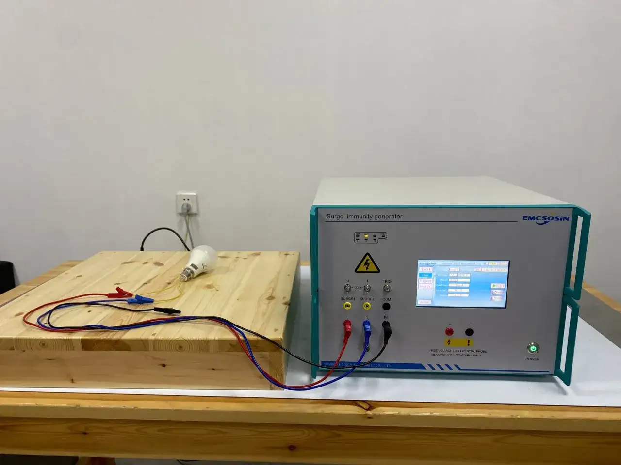
How a surge immunity test is run
- I define the exact equipment under test, its operating mode, and the ports that matter in the field.
- I decide whether the stress enters through mains power, control wiring, or a communication line, because each route behaves differently.
- I set the level, polarity, repetition pattern, and duration before anything is energised.
- I monitor the device while the pulses are applied, not only afterwards, because many failures show up as dropouts, resets, or corrupted comms rather than a dead unit.
- I compare the outcome against a pass/fail rule that was agreed before the test began.
The coupling/decoupling network is the part that makes this meaningful: it injects the transient into the selected path while keeping the rest of the setup from becoming part of the fault. In practice, I want the arrangement to resemble the real installation as closely as possible, including cable length, enclosure type, and grounding, because a neat bench setup can give you a very optimistic result.
What I lock down before the first pulse is simple but easy to miss: the device configuration, the load condition, the cable layout, and the exact operating state. If the product will live in a metal enclosure, beside variable-speed drives, or on a long field cable, the test should reflect that reality. Otherwise the result is technically correct and practically misleading.
That is why the next step is choosing the right protection architecture, not just the right test level.How to choose the right protection approach
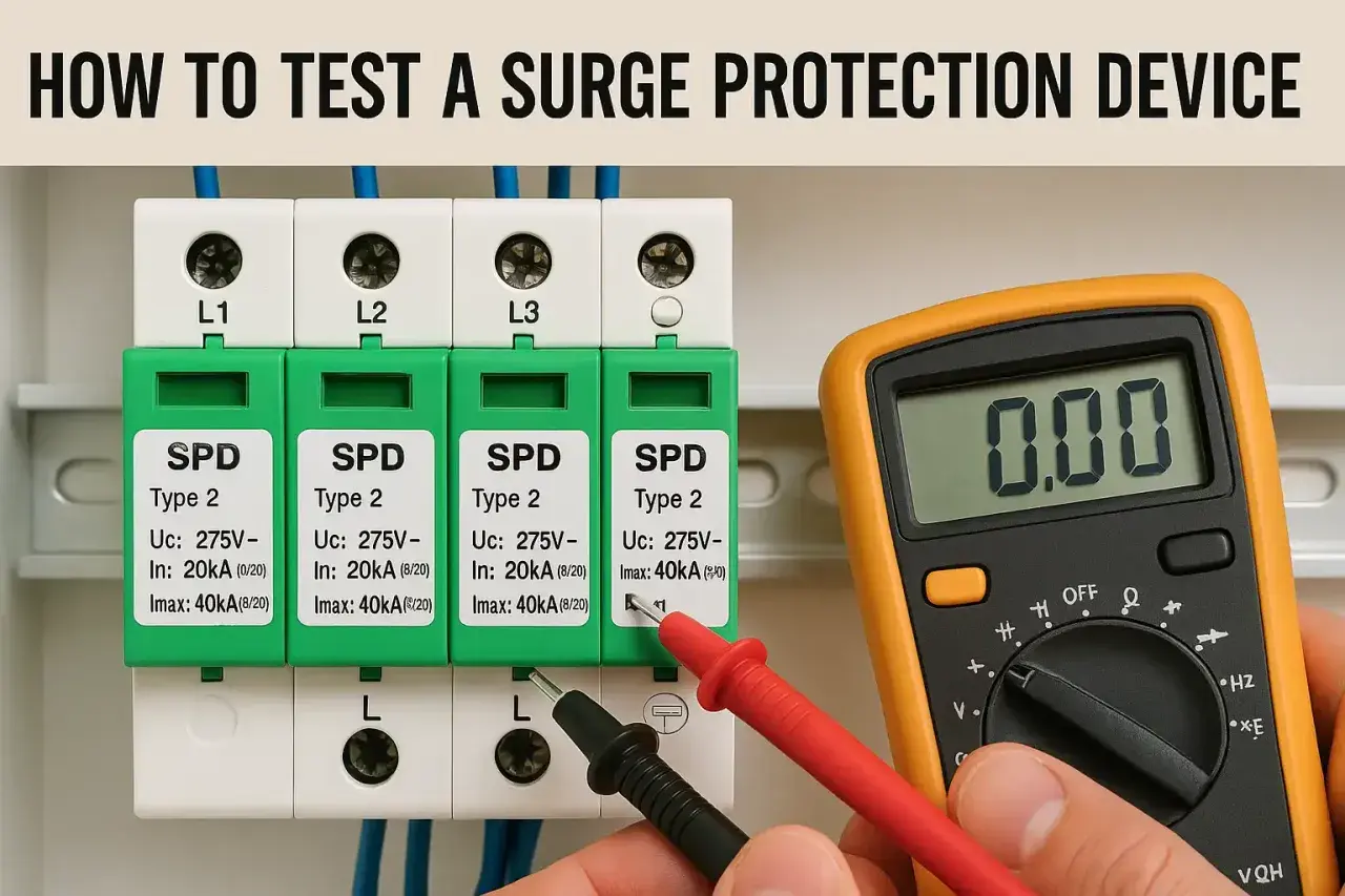
I usually think in layers. The first layer is the entry point, the second is the distribution board or panel, and the third is local protection close to the load; that is why Type 1, Type 2, and Type 3 devices are used together rather than as interchangeable substitutes.
| SPD type | Typical location | What it is good at | What it cannot fix |
|---|---|---|---|
| Type 1 | Origin of the installation, such as the main distribution board | Handling the highest-energy incoming events and forming the first barrier | It still needs coordination with downstream devices and good bonding |
| Type 2 | Sub-distribution boards and consumer units | Protecting branch circuits and the equipment fed from them | It may leave sensitive loads exposed if they sit far from the board |
| Type 3 | Close to the load | Fine protection for vulnerable electronics | It should supplement Type 2, not replace it |
What people often miss is coordination. A larger device on paper does not automatically improve real resilience if the bonding is poor, the cable runs are too long, or the downstream equipment is outside the protection zone. I also check whether data lines, fieldbus links, and telemetry pairs have their own path to protection, because a mains SPD will not stop a transient from arriving through Ethernet or a remote sensor cable. If space in an existing board is tight, an external enclosure is often the cleaner retrofit choice than forcing a compromise.
The practical rule is simple: one strong device does not make up for a weak installation. The system has to work as a system, and that leads straight into the kinds of failures I look for.
Common failure modes that reveal weak designs
The most useful failures are the ones that teach you something. In automation and smart-building systems, I look for behaviour that seems minor at first and then turns into downtime later.
| Observed symptom | What it usually points to | Why it matters |
|---|---|---|
| Reset or reboot | PSU hold-up is too short or suppression is marginal | The system may appear fine, but production logic or communications are interrupted |
| Communication dropout | Transient coupling onto data pairs or poor bonding | Edge devices, PLC links, and telemetry can fail even when the main supply stays up |
| False trip or nuisance shutdown | Control supply instability | Creates avoidable downtime and hides the real root cause |
| Latent damage | Components were stressed but did not fail immediately | Margin has been lost, so the next event may finish the job |
The dangerous pattern is latent damage: the unit seems fine after the test, but its margin has narrowed and it starts failing later under real site noise. That is especially important for IoT gateways and control panels, because one unstable node can look like a networking problem when the real issue is transient stress on the power path.
Once you know what a weak design looks like, the report itself becomes much more valuable, because it can tell you whether the weakness is in the device, the installation, or the way the test was set up.
What I want in a useful test report
A report is only useful if someone can reproduce the decision from it. I want to see:
- The exact equipment revision and hardware configuration.
- The operating state used during the test, including load conditions.
- The applied levels, polarity, and number of pulses.
- The ports tested and the coupling path used for each one.
- The pass/fail rule, plus any resets, alarms, or brief interruptions that were observed.
- The calibration status of the setup and any deviations from the intended arrangement.
If those details are missing, the report may still prove that a test happened, but it will not help you judge whether the result applies to production units or a field retrofit. That is the difference between paperwork and engineering evidence.
For industrial users, I would add one more layer: the test should say whether the result is valid for the way the equipment will actually be deployed, not just for a clean bench build. A good report saves time later because it prevents you from repeating the same argument after installation.
The checks I would make before sign-off
Before I sign off a panel, I check three things: the protection layers are coordinated, the earthing and bonding path is deliberate rather than incidental, and the control system has been tested in the mode it will actually run in. If any of those change later, I expect the result to be revisited.
The best way to think about transient resilience is as part of the installation architecture, not a single component choice. If I were building or upgrading a system in 2026, that is the lens I would use to avoid resets, nuisance trips, and expensive call-outs.