The essentials at a glance
- It measures insulation resistance by applying DC voltage and watching for leakage current.
- In UK low-voltage work, 500 V DC is common, while 250 V DC may be used where sensitive equipment could be harmed.
- For many BS 7671 low-voltage tests, 1 MΩ is the familiar minimum, but the trend over time matters just as much.
- The circuit must be isolated first; this is not a live test.
- Good readings do not prove every fault is absent, only that the insulation is behaving acceptably under test conditions.
What the test is actually checking
At its core, the test is simple. The instrument applies a known DC voltage and measures how much current leaks through the insulation. If the insulation is sound, leakage stays tiny and resistance stays high; if the insulation is degraded, resistance drops.
People often use “Megger” as shorthand for the tester itself, but the job being done is insulation resistance measurement. That distinction matters, because a continuity test confirms that a path exists, while this test checks that unwanted paths do not.
In practical terms, I am looking for the health of the barrier between conductors, between conductors and earth, and between parts of a system that should be electrically separate. That is why the test is so useful in electrical systems that have to run reliably under heat, vibration, dust, or moisture.
That leads directly to the next question: how does the tester create a reading that is useful enough to trust?
How the test works in a real circuit
The tester sends DC voltage between conductors or between conductors and earth, then calculates resistance from the current it sees. On a healthy circuit, the current is so small that the instrument reports a very high resistance value; on a compromised circuit, leakage current rises and the displayed resistance falls.
That DC approach is useful because it exposes leakage paths that may not show up with a simple multimeter. It also gives a more meaningful picture of cable insulation, motor windings, and switchgear than resistance testing with a low-voltage ohmmeter ever could.
One practical detail matters more than many beginners realise: the test can leave a charge in the insulation after the reading is taken. I always treat discharge as part of the test, not an optional extra, because a cable or motor can hold enough energy to give a nasty surprise if it is handled too soon.
On dirtier or longer circuits, a guard terminal can help separate surface leakage from the insulation path itself, which is useful when I need a cleaner reading on contaminated equipment. That matters most when the next step is deciding where in the system the test should be used.
Where I would use it in an electrical system
I reach for insulation resistance testing in places where degradation starts quietly and becomes expensive later. The method is especially useful during commissioning, periodic inspection, after maintenance, and when fault-finding on equipment that has been exposed to moisture or heat.
| Asset | Why I test it | What I am trying to catch |
|---|---|---|
| Cables and final circuits | To confirm insulation between live conductors and earth | Moisture ingress, nicked insulation, crushed cable, contamination |
| Motors and pumps | To check windings before startup or after storage | Damp windings, ageing varnish, oil, dust, thermal stress |
| Switchgear and distribution boards | To verify integrity after installation or maintenance | Tracking, dirt, carbon paths, loose contamination |
| Control panels and automation wiring | To identify faults before commissioning | Accidental damage, moisture, poor terminations, cable faults |
| Outdoor and plant-room equipment | To check systems exposed to harsh environments | Condensation, salt, oil, heat-related insulation decline |
I would not use it blindly on live electronic assemblies. PLCs, drives, meters, surge protective devices, and other solid-state devices can be damaged by the applied test voltage unless they are isolated or the manufacturer specifically allows the test.
Once I know where the test belongs, the real value comes from doing it safely and in the right sequence.
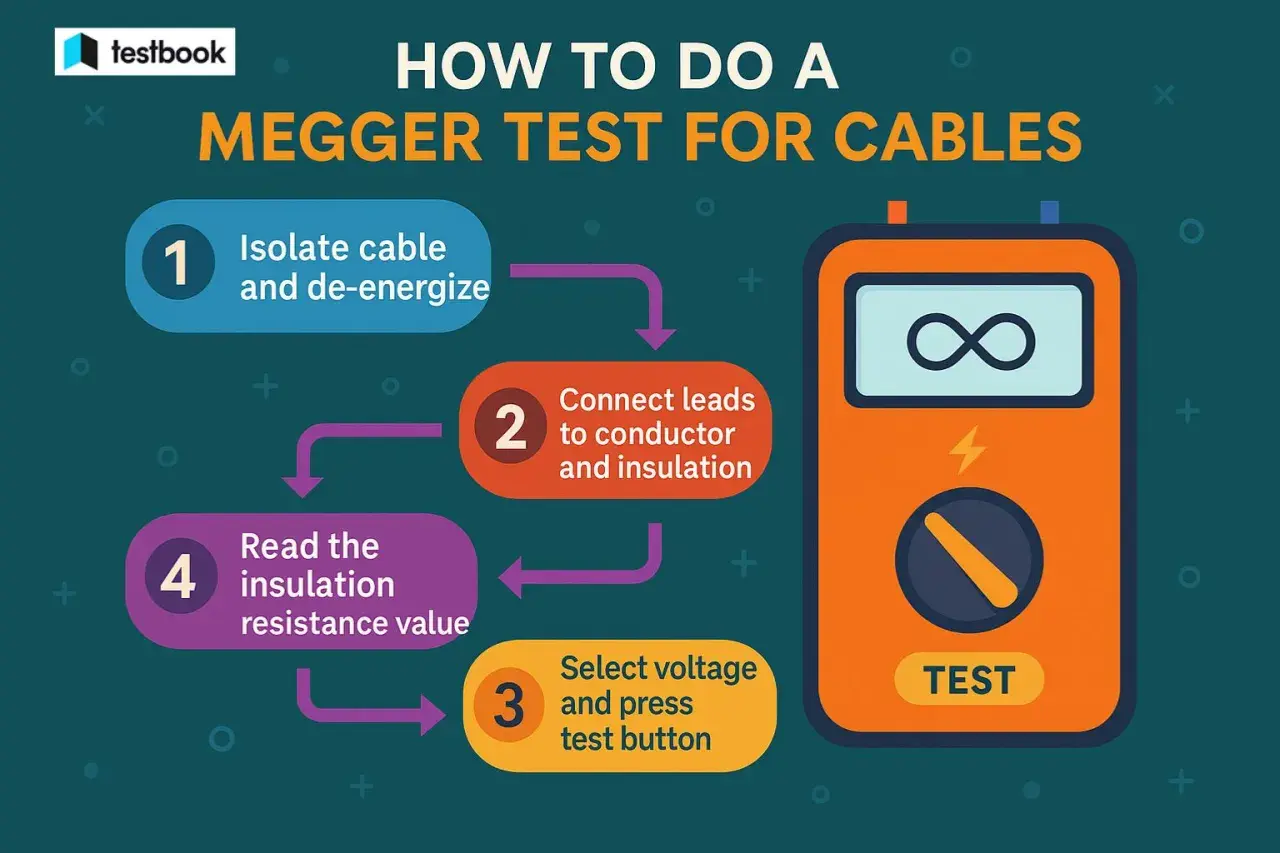
How to carry out a safe test step by step
The test is only as good as the setup. A rushed Megger test can damage equipment, produce a false reading, or give a false sense of security, so I keep the process disciplined.
- Isolate and lock off the supply.
- Prove dead with suitable test equipment.
- Disconnect or protect sensitive electronics, including SPDs, drives, PLCs, dimmers, and monitoring devices.
- Select the correct test voltage for the circuit and equipment.
- Connect the leads between live conductors and earth, and between conductors where required.
- Hold the test long enough for the reading to settle, then record the value.
- Release the test, allow the insulation to discharge, and verify that it is safe before touching anything.
For many UK low-voltage circuits, 500 V DC is the normal choice, while 250 V DC is used where the circuit or connected equipment could be damaged. Higher test voltages are reserved for equipment and systems that are designed for them, not chosen simply because a bigger number feels more impressive.
There is one more detail I always record: the condition of the circuit at the time of the test. Temperature, humidity, and recent cleaning or drying can all affect the result enough to matter later.
That is why a raw number needs interpretation, not just collection.
How to read the number without fooling yourself
Reading insulation resistance is partly technical and partly contextual. A circuit can technically “pass” and still deserve attention if the value is trending down from previous tests or if it sits uncomfortably close to the threshold.
| Reading pattern | What it usually means | What I would do next |
|---|---|---|
| Very high and stable | Insulation is probably healthy | Record the result as a baseline for future comparison |
| Around 1 MΩ | Borderline for many low-voltage UK tests | Inspect for moisture, contamination, or mechanical damage |
| Below 1 MΩ | Usually a fail or an urgent investigation | Do not energise until the cause is found and corrected |
| Reading climbs during the test | Normal polarization behaviour on healthy insulation | Use the final settled value, not the first number displayed |
| Reading is unstable or falls suddenly | Moisture, contamination, wrong setup, or connected electronics | Recheck the isolation and look for external causes |
For larger motors and generators, I also pay attention to time-based diagnostics such as PI, the polarization index, and DAR, the dielectric absorption ratio. Those measures compare readings taken over time, which can be more revealing than a single snapshot when windings need to dry, settle, or show early deterioration.
The next pitfall is assuming that a passing value means the whole job is done.
Common mistakes and limits I would not ignore
- Testing circuits that still contain sensitive electronics.
- Forgetting that moisture, dirt, temperature, and cable length change the reading.
- Assuming one good result proves the entire system is free from faults.
- Ignoring discharge after the test and treating the circuit as safe too early.
- Using the test as the only diagnostic tool for complex equipment.
This is where experience matters. Insulation resistance testing is excellent at spotting deterioration in the insulation path, but it will not reliably expose every loose termination, intermittent arc, or turn-to-turn winding fault. On a healthy-looking machine, those problems may need thermal inspection, visual checks, continuity testing, or manufacturer-specific diagnostics as well.
I treat the test as one strong signal in a wider maintenance picture, not as a full electrical health certificate. That mindset fits UK practice well, which is the next layer to keep in view.
How UK practice frames the test in 2026
In UK electrical work, this test sits inside installation verification and periodic inspection rather than as an isolated ritual. The IET’s BS 7671 guidance still uses 1 MΩ as the general minimum for many low-voltage circuits, and HSE guidance keeps the focus on safe isolation, competent testers, and controlled testing conditions.
In practical terms, I choose 250 V DC where the circuit or connected equipment could be damaged, 500 V DC for many 230/400 V circuits, and a higher test voltage only when the equipment rating and manufacturer instructions justify it. That is especially important in industrial automation, where drives, controllers, and monitoring gear are often mixed with plain copper wiring in the same cabinet.
UK electricians also pay close attention to the condition of the installation before testing. If surge protection, electronic controls, or other sensitive devices cannot be removed or isolated, the test plan has to adapt rather than forcing a standard procedure onto the wrong circuit.
That leaves one final question that matters in the real world: when do I trust the result, and when do I keep digging?
What I check before I trust the result
I never rely on a single number in isolation. I compare phase-to-earth readings, phase-to-phase readings, and the result against previous records, because a weakening trend often tells me more than the absolute value on the day.
If the reading is borderline, I inspect terminations, cable glands, moisture paths, and signs of contamination before I sign anything off. On outdoor equipment, plant-room gear, or motors that have stood idle, I also want to know whether the unit was recently dried, cleaned, or warmed up, because those conditions can improve the number without fixing the underlying issue.
Used that way, the test becomes more than a box-ticking exercise. It gives me a realistic view of whether the system is safe to energise now, or whether it deserves another round of inspection before power goes back on.