The short version is that overvoltage is voltage above the safe operating limit
- Transient overvoltage is usually a very fast spike, often tied to lightning or switching events.
- Temporary overvoltage lasts longer and often points to a supply or neutral problem.
- Sustained overvoltage is a high supply that stays elevated long enough to heat and age equipment.
- In the UK, the nominal mains supply is 230V, with a common supply band of 216V to 253V at the supply point.
- Breakers and fuses are not overvoltage protection; they mainly protect against excess current.
- For automation and IoT systems, the right fix is usually a mix of surge protection, monitoring, and maintenance, not a single device.
What overvoltage is, and what it is not
I separate overvoltage into three practical cases. A transient event is a short spike that may last microseconds or milliseconds. A temporary event lasts longer, often seconds to minutes, and usually points to a supply issue rather than a one-off surge. A sustained condition is the most worrying because the voltage stays too high long enough to stress insulation, power supplies, and motors.
| Type | Typical duration | Common causes | Typical effect |
|---|---|---|---|
| Transient overvoltage | Microseconds to milliseconds | Lightning, switching motors, capacitor banks, inductive loads | Semiconductor damage, nuisance faults, insulation stress |
| Temporary overvoltage | Seconds to minutes | Neutral faults, regulation issues, network disturbances | Heating, alarms, device resets, premature wear |
| Sustained overvoltage | Minutes to hours | Tap setting errors, feeder problems, local generation effects | Accelerated ageing, equipment failure, fire risk |
In the UK, that distinction matters because the supply is not a fixed 230V at every socket all the time. The usual band at the supply point is 216V to 253V, so a reading near the top of that range is not automatically a fault. It can still be too high for some downstream devices, especially once local wiring, voltage rise, and sensitive electronics are taken into account.
I also keep the event itself separate from the way standards classify installation environments. In practice, the rating tells you how much transient stress a device should tolerate in a given part of the distribution chain; it is not the same thing as a live overvoltage event. Mixing those two ideas is a common way to choose the wrong protection.
Once that distinction is clear, the next step is to find the source of the excess voltage.
Why it happens in UK electrical systems
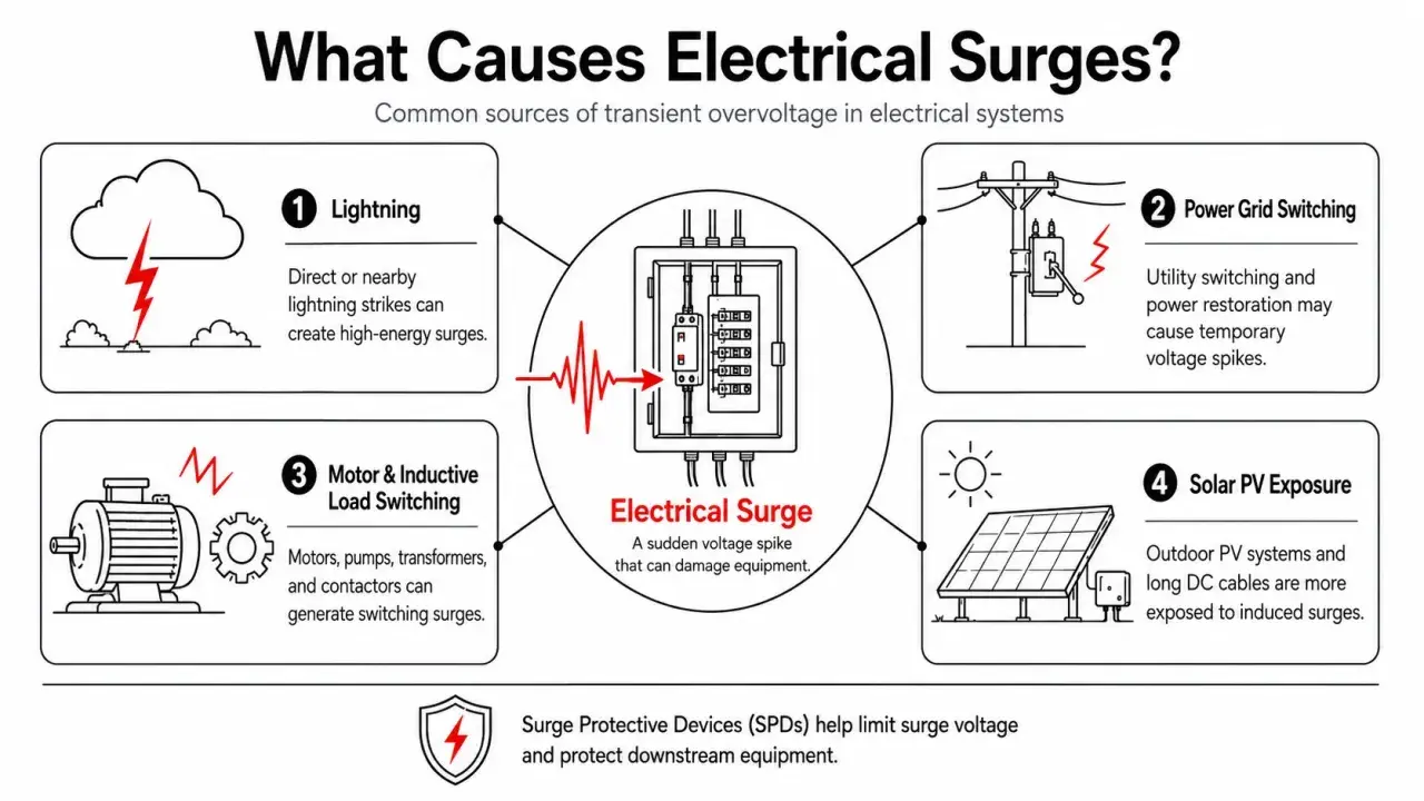
On UK sites, I usually see the same handful of causes. Some are external, like lightning or network disturbances. Others are created inside the installation itself, which is why a problem can feel intermittent and hard to pin down.
- Lightning and nearby strikes can induce very fast surges into power and data lines, even when the strike is not directly on the building.
- Switching events from motors, contactors, transformers, and capacitor banks can create sharp spikes when current changes suddenly.
- Neutral faults or loose terminations can shift phase voltages and push one part of a three-phase installation above normal while another part drops below it.
- Local solar generation can raise voltage on sunny low-load days, especially on weaker feeders where export has less room to absorb the rise.
- Supply regulation issues or transformer tap settings can leave a feeder running consistently high, even though the site owner only sees the effect at the point of use.
- Inductive loads in automation and manufacturing plants can generate internal transients when they are switched off, which is why cabinets often need more than one layer of protection.
In a UK industrial or commercial building, that list is not academic. A rooftop PV array, a long feeder, and a few large motors can create the kind of local voltage rise that does not show up in a quick walkaround but still punishes electronics over time. The source matters because each one leaves a different damage pattern behind.
That is why the next question is not just where the extra voltage came from, but what it does once it gets inside the system.
What it does to equipment and production
Overvoltage does not always fail dramatically. In many cases, it chips away at reliability: a PLC reboots, a drive throws a fault, an LED driver runs hot, or a sensor drops off the network and comes back minutes later. Those are often the early signs, and they are easy to dismiss until they start repeating.
| Equipment | What overvoltage often looks like | Why it matters |
|---|---|---|
| Power supplies, PLCs, HMIs, IoT gateways | Resets, comms loss, corrupted data, early capacitor failure | One brief event can stop monitoring or control across a whole line |
| Variable-speed drives and servo systems | DC bus alarms, nuisance trips, stressed input stages | Production stops even when the motor itself is still healthy |
| Motors, contactors, and relays | Hotter operation, insulation stress, contact wear | Shorter service life and more maintenance calls |
| LED lighting and electronic drivers | Flicker, dimming issues, premature driver failure | Maintenance costs rise long before a full outage appears |
| Data and communication lines | Packet errors, dropped links, intermittent fieldbus faults | Automation systems become unstable in ways that look like software bugs |
A breaker can stay closed while all of this is happening. That is the trap. Current protection devices are built to respond to overcurrent, not excess voltage, so they may not react at all while the equipment is being stressed. In industrial environments, that difference is expensive because the damage often appears as downtime rather than a clean shutdown.
I also pay attention to the distinction between supply-side overvoltage and internal DC-bus overvoltage. A drive can trip because of regeneration or a power quality event even when the mains reading looks acceptable at a glance. That is one reason I never diagnose this problem from a single meter reading.
That is why the next step is to prove whether the site has a real voltage issue, a transient issue, or just a misleading snapshot.
How to tell a real overvoltage event from normal mains variation
On a UK site, I start with measurement, not assumptions. A single reading from a handheld meter can be useful, but it can also hide the actual problem if the event is brief or intermittent. I want to know where the voltage was measured, when it was measured, and whether the reading repeats under the same load conditions.
- Measure at the point of supply first, then compare that reading with distribution boards and the load itself.
- Check whether the reading sits above 253V at the supply point, or whether it only rises locally after wiring losses are added.
- Use a logging meter or power quality analyser if the issue comes and goes, because fast spikes often disappear before a handheld meter can catch them.
- Look for timing patterns, such as events that line up with sunny PV export, motor starts, contactor switching, or storms.
- Inspect neutral connections, terminations, and earthing paths if one phase or one section of the site behaves differently from the rest.
| Clue | What it may suggest | What I would check next |
|---|---|---|
| Voltage rises when rooftop PV is exporting | Local feeder rise | Inverter settings, cable length, feeder capacity, point of connection |
| One phase reads much higher than the others | Neutral fault or imbalance | Neutral terminations, service head, upstream supply condition |
| Devices fail after storms or switching events | Transient surges | SPD coordination, cable routing, bonding, lightning exposure |
| Drives show DC bus overvoltage alarms | Regeneration or supply spike | Braking circuit, mains quality, drive sizing, machine duty cycle |
A handheld meter is useful, but it is not enough when the problem is a microsecond spike or a fault that comes and goes with load changes. Once you can identify the pattern, the protection choices become much clearer.
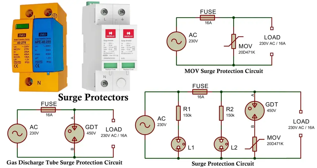
Protection that actually works in industrial and building systems
I do not like one-device answers here, because they usually fail in real life. Good protection is layered. The right setup depends on where the energy enters the site, how sensitive the load is, and whether the threat is a brief surge or a longer overvoltage condition. In practice, I combine surge suppression, monitoring, and maintenance rather than treating them as interchangeable.
| Protection method | Best use | Limitation |
|---|---|---|
| Type 1 SPD | At the origin where lightning and service-entry surges can enter | Not a fix for sustained high supply voltage |
| Type 2 SPD | At sub-distribution boards feeding control panels, drives, and general loads | Needs correct coordination with upstream and downstream devices |
| Type 3 SPD | Close to sensitive equipment such as PLCs, gateways, and instrumentation | Works best as the last layer, not the only one |
| Voltage monitoring relay | For disconnecting or alarming when the supply stays too high | Does not absorb a surge; it only reacts to what it measures |
| UPS or power conditioning | For control gear, comms, and critical IT loads | Can bridge interruptions, but it will not cure feeder problems |
| Earthing and neutral maintenance | For reducing hidden faults that create dangerous voltage shifts | Needs inspection, not just installation |
The IET’s guidance separates Type 1, Type 2, and Type 3 SPDs by installation point, and that placement matters more than a product label. I usually protect both the power feed and the signal paths in automation cabinets, because many “power” problems enter through data lines or field devices rather than the main supply alone.
No single device solves every case. An SPD is excellent at clamping transients, but it will not make a feeder sitting too high become normal, and a voltage relay will not absorb a lightning-induced spike. If the installation needs both functions, it is better to say that plainly and design for it.
With the right mix in place, the remaining task is to decide what to inspect first on site.
The checks I would make first on a UK site
When I walk into a UK building or industrial plant with suspected overvoltage problems, I keep the first pass simple and disciplined. I want to know whether the issue is at the supply, in the installation, or at the load. That usually saves more time than chasing the most expensive-looking component first.
- Check the voltage at the point of supply and compare it with the normal 216V to 253V band.
- Inspect neutral terminations, earthing, and signs of heat or looseness at the service entry and main boards.
- Review whether PV export, capacitor switching, motor starts, or other load changes line up with the symptoms.
- Confirm that SPDs are installed at the right points and have not degraded or failed silently.
- Log the problem long enough to catch the real pattern instead of relying on a one-off reading.
If the reading is only slightly high but stable, I look at feeder design and local voltage rise first; if it is spiking, I look at transient protection and coordination; if it is sustained, I treat it as a supply problem until proven otherwise. That distinction is the difference between replacing equipment one by one and solving the actual fault.