Insulation that leaks to earth is one of those faults that can sit quietly for months before it turns into nuisance tripping, overheating, or a hard failure. An earth insulation resistance test tells you whether the live conductors are still properly separated from earth and from each other, which is why it matters on domestic circuits, industrial panels, motor feeders, and control gear alike. In UK practice, the real value is not just the number on the tester; it is knowing which voltage to use, what the reading means, and when the test itself can mislead you.
What matters most before you trust the reading
- The test checks for unwanted leakage from live conductors to earth and between conductors.
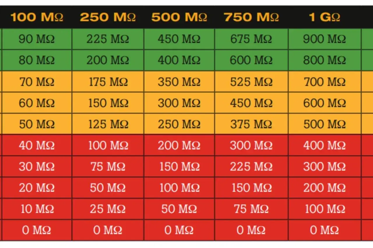
- For most UK low-voltage circuits up to 500 V, the usual test is 500 V DC with a minimum result of 1 MΩ.
- If SPDs or sensitive equipment cannot be disconnected, the circuit may be tested at 250 V DC, but it still needs at least 1 MΩ.
- SELV and PELV circuits are normally tested at 250 V DC with a minimum of 0.5 MΩ.
- A low reading is not always a bad cable. Moisture, electronics, borrowed neutrals, and parallel paths can all distort the result.
- The insulation test is only one part of verification. It does not replace continuity, polarity, or earth fault loop testing.
What this test really measures
At its core, the test measures leakage through insulation, not continuity through a conductor. I use it to check that current is staying inside the intended path and is not sneaking to protective earth because of damaged cable, contamination, moisture, crushed insulation, failing accessories, or carbon tracking.
That distinction matters. A good insulation reading does not prove the protective conductor is continuous, and it does not prove an RCD will trip at the right time. It simply tells me that the insulation system is doing its job well enough for the circuit to be energised with confidence.
On modern plant, the same principle applies to motors, heater banks, PLC panels, sensor enclosures, and field wiring. The test is useful precisely because it exposes weak spots before they become faults you can hear, smell, or feel.
If I get a low reading, I do not jump straight to a failed cable. I first ask whether there is a parallel path, an electronic device still connected, or a damp component changing the result. That leads straight into the choice of test voltage and the way the circuit is prepared.
How to choose the right test voltage in UK installations
BS 7671 ties the test voltage to the nominal voltage of the circuit. In day-to-day work, that means most low-voltage installations are tested at 500 V DC, while extra-low-voltage circuits get a lower voltage to avoid unnecessary stress.
| Circuit type | Usual test voltage | Minimum acceptable reading | Practical use |
|---|---|---|---|
| SELV and PELV | 250 V DC | 0.5 MΩ | Extra-low-voltage control and safety circuits |
| Up to 500 V, excluding SELV/PELV | 500 V DC | 1 MΩ | Most domestic, commercial, and industrial low-voltage circuits |
| Above 500 V | 1000 V DC | 1 MΩ | Higher-voltage fixed installations |
Where SPDs or equipment likely to be damaged are connected, I disconnect them first. If that is not reasonably practicable, the circuit may be tested at 250 V DC, but the reading still needs to be at least 1 MΩ. I treat that as a compromise, not a shortcut.
That is the point many people miss. The test voltage is not chosen to make the reading look good. It is chosen to verify insulation without damaging the circuit or creating a false failure. Once the voltage is right, the way the circuit is prepared becomes the deciding factor.
How I would carry out the test step by step
My routine is deliberately boring. The best insulation tests are the ones that do not depend on luck.
1. Isolate and inspect first
I isolate the supply, lock off where required, and prove dead before I touch the circuit. Then I look for obvious issues first: water ingress, overheated terminations, cracked accessories, signs of carbon tracking, and anything else that would explain a poor result before I even start testing.
2. Remove what can distort the result
Before I apply the tester, I disconnect or isolate equipment that can be damaged by the test voltage or that can create parallel leakage paths. That often includes SPDs, dimmers, electronic drivers, variable-speed drives, UPS units, smart relays, sensors, and some control modules. If the manufacturer says a device should not see the test voltage, I take that seriously.
3. Make the standard connection
For a normal verification test, I link the live conductors together, usually line and neutral, and test them against the protective conductor or earthing arrangement. That gives me a reading for the circuit as a whole rather than one conductor at a time, which is the most useful result when I want to know whether the installation is safe to energise.
When I am fault-finding, I may separate the circuit and test line to earth, neutral to earth, and line to neutral individually. That is slower, but it helps localise whether the issue sits in a cable run, a fitting, a junction box, or a connected device.
Read Also: Electrical Suction Explained - Beyond the Pump Rating
4. Test, stabilise, and record
I apply the selected voltage, let the reading settle, and record both the value and the test voltage. If I am working on an industrial panel or a building with several similar circuits, I note the results in a way that makes comparison possible later. One number by itself is useful; a trend over time is better.
If the result looks strange, I do not just retest the same way and hope for a different answer. I break the circuit into sections, remove suspect accessories, and repeat the measurement until the weak point shows itself. That is usually faster than guessing.
Why readings fall even when the cable looks fine
When the number looks wrong, the fault is not always where the tester points. Insulation resistance is sensitive to moisture, contamination, heat, and anything else that creates a parallel leakage path, so I always read the result in context.
| Reading pattern | Likely cause | What I check first |
|---|---|---|
| Low after rain or in an outdoor enclosure | Moisture or condensation | Glands, seals, drainage, heaters, and any damp junctions |
| Low only when the circuit is fully assembled | Connected electronics or SPDs | Disconnect vulnerable devices and retest |
| Low across several related circuits | Shared neutral, cross-connection, or parallel path | Map the neutrals and split the circuits cleanly |
| Very low from the first press of the test button | Direct insulation damage | Cable, terminal, accessory, or junction box inspection |
| Reading changes a lot between test attempts | Loose connection, contamination, or unstable leakage path | Terminations, damp surfaces, and surface tracking |
Temperature matters too. A warm enclosure or a humid plant room can read lower than the same circuit on a dry day, so I avoid treating borderline results as if they were absolute truth. If I need confidence, I compare like with like, not a damp morning with a dry afternoon.
That is also why I am cautious with large installations. Lots of small leakage paths in parallel can make a whole-board reading look weaker than an individual circuit. In those cases, subdivision is not overkill. It is the fastest way to find the real problem.
How I read pass, borderline, and fail results
1 MΩ is the floor, not the finish line. If a circuit barely clears the limit, I do not treat it as healthy without further thought. I compare it with adjacent circuits, previous records, and the installation environment.
| Result pattern | How I read it | Next step |
|---|---|---|
| Well above the minimum and stable | Usually satisfactory | Record it and move on with the rest of the verification |
| Above the minimum but far lower than expected | Possible early warning | Check moisture, contamination, and hidden parallel paths |
| Below the minimum | Unsatisfactory | Keep the circuit isolated, find the defect, and retest after repair |
| Good on one section, poor on another | Localised fault | Split the circuit and narrow the problem down methodically |
On an EICR, I do not let the code drive the diagnosis. The defect drives the code. A genuinely unsatisfactory result needs investigation and likely remedial work, but the classification depends on what is actually wrong, not just on the number alone.
This is where a good test record earns its keep. If a circuit used to read comfortably high and now sits close to the threshold, that change matters even if the circuit has not yet failed. I care about movement, not just compliance.
Why modern automation gear changes the picture
Modern industrial and connected systems make the test more nuanced than it used to be. Drives, filters, power supplies, battery chargers, smart relays, building controllers, energy meters, and many sensor modules can create leakage paths or be upset by the test voltage even when the installation is otherwise sound.
That matters in factories, plant rooms, and smart buildings where a single panel might contain both robust power circuits and delicate low-voltage electronics. A cable run to a motor may tolerate the standard 500 V DC test quite happily, while the PLC side of the same panel should be handled differently.
- I disconnect electronics when the manufacturer says they should not see the test voltage.
- I use 250 V DC when SPDs or vulnerable devices cannot reasonably be removed and the standard allows that approach.
- I check whether a control circuit has filtering or power electronics that can create normal earth leakage, because that can make a healthy circuit look weaker than it is.
- On larger panels, I may use the tester’s guard terminal if available, because it helps reduce surface leakage from dirt or damp and makes the result easier to trust.
- After a repair, I repeat the test with the same setup so the before-and-after readings are comparable.
The practical takeaway is simple: modern equipment does not make the test less useful, but it does make preparation more important. If the circuit is full of electronics, the test should be planned, not improvised.
The checks I make before re-energising the circuit
When the reading is satisfactory, I still do not rush straight back to energisation. I confirm that the fault has been explained, not just hidden, then I retest any section that was disturbed and keep the result in a format that can be compared later. A single number matters less than a pattern: a stable high reading over time tells me the insulation is healthy, while a slow decline tells me to look for moisture ingress, thermal stress, or a component beginning to age out.
For UK installations, that is the practical mindset that keeps the test useful. Isolate properly, choose the right voltage, disconnect what can distort the result, and treat the reading as evidence rather than a verdict. If the figure is borderline or unstable, split the circuit and find the weak point instead of hoping the number improves next time.
That approach saves time, reduces unnecessary repeat visits, and gives you a far better chance of catching a developing fault before it becomes a shutdown or a safety issue.