The checks that separate a useful winding reading from a misleading one
- Use a true four-wire low-resistance meter; a standard multimeter is usually not precise enough at milliohm levels.
- Record temperature, lead setup, and motor configuration so you can compare like for like later.
- Balanced phase readings are the goal; a spread of more than a few percent deserves a closer look.
- This test finds loose joints, open circuits, bad crimps, and phase imbalance, but it does not replace insulation or surge testing.
- It is most valuable after a repair, during commissioning, or when a drive starts running hotter or less smoothly than expected.
Why winding resistance matters in motion control
On a three-phase motor, the winding path is supposed to be electrically symmetrical. When it is not, current distribution shifts, heat rises, and the control system starts working against a problem that should have been caught earlier. In a UK plant with 400 V drives, that can show up as slower response, uneven torque, repeated overloads, or a servo that never quite settles cleanly.
I care about this test because it gives me a fast read on the integrity of the motor’s conductive path. If one phase is higher than the others, I start thinking about loose lugs, a poor crimp, corrosion, a damaged joint, or an internal connection issue. If one phase is noticeably lower, I become more cautious: that can point to a wiring mistake, a parallel path, or an internal fault that needs more than a casual retest.
- Torque balance depends on balanced windings, especially on servo axes and conveyor drives.
- Heat management gets worse when one phase carries more stress than the rest.
- Reliability improves when you catch a resistance mismatch before it becomes a stop in production.
That is why the setup matters before you touch the meter.
How I would run it safely
I never treat this as a casual continuity check. A proper low-ohm measurement starts with isolation, because the meter is meant to measure the winding only, not the rest of the circuit around it. For motion-control systems, that usually means disconnecting the motor from the drive, proving the circuit is dead, and making sure any linked control gear will not feed back into the measurement.
Isolate the motor properly
- Lock out and tag out the supply.
- Verify zero voltage at the motor terminals with an approved tester.
- Disconnect the motor from the drive or inverter unless the OEM procedure says otherwise.
- Let the machine cool enough for a meaningful reading if it has just come off load.
- Record the motor temperature and the terminal arrangement before you start.
The temperature note matters more than many people realise. Resistance shifts with heat, so a warm motor can look different from a cold one even when nothing is actually wrong. I want the reading to reflect the motor, not the last thirty minutes of production.
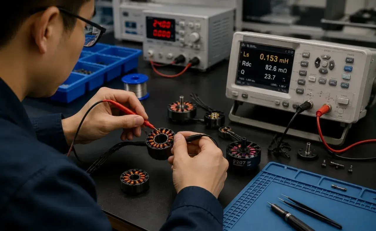
Choose the right meter
Megger’s low-resistance guidance is clear on the core point: a true four-terminal Kelvin measurement is what removes lead resistance and contact resistance from the result. That matters here because the winding itself is often only a fraction of an ohm, so the probe and lead losses can distort the number if you use the wrong tool.
- Use a low-resistance ohmmeter, not a general-purpose DMM.
- Prefer Kelvin clips or four-wire leads.
- Pick a meter with stable current output and, if available, current reversal to reduce thermal EMF effects.
- Keep the leads short, clean, and tightly attached to the same points each time.
In practice, I want enough test current to get a stable reading without heating the winding. If the instrument needs a long settle time or the number drifts as the winding warms, I stop and correct the setup rather than trusting a shaky result. Once the setup is clean, the reading becomes much easier to trust.
Read Also: Protect Motor Controllers - Stop Corrosion Failures Now
Take the measurements in a repeatable order
On a six-lead motor, I measure each winding separately. On star or delta-connected machines, I follow the wiring diagram and the terminal box arrangement rather than guessing. The point is not just to get a number; it is to get the same number in the same way every time so the result can be compared later.
I usually take each measurement twice if the spread looks suspicious. If the second reading lands in the same place, I trust the issue more than the meter. If the reading moves around, I look at the clips, the joint cleanliness, and whether the motor is still changing temperature.
When the setup is stable, the result becomes much more useful. That leads straight into the question most teams ask next: what does a good or bad number actually look like?
What the readings actually tell you
The simplest pass/fail rule is this: the phases should be closely matched, and the result should agree with the motor’s history and manufacturer data. A small amount of variation is normal. A pattern that keeps showing up on one phase is not normal, even if the motor still runs.
Fluke’s field guidance is useful here: if phase-to-phase readings differ by more than a few percent, I treat the motor as questionable until the cause is explained. I would not condemn it on a single imperfect reading, but I would not energise it and hope for the best either.
| Reading pattern | What it usually suggests | What I would check next |
|---|---|---|
| All phases close together | The winding path is probably healthy and the terminations are consistent | Compare with the baseline, then move on to insulation resistance or other planned tests |
| One phase higher than the others | Loose joint, poor crimp, corrosion, or partial open circuit | Inspect the terminal box, lugs, splices, and any junctions in the cable run |
| One phase lower than the others | Possible internal fault, wiring error, or unintended parallel path | Verify the connection diagram and retest after removing any extra circuit paths |
| Numbers drift during the test | Poor contact, lead movement, or a winding that is warming up | Clean the contact points, shorten the lead run, and repeat the measurement |
| Large change versus previous records | The motor, the connections, or both have changed enough to matter | Treat it as a maintenance event and investigate before returning it to service |
What this test does not do is just as important. It will not reliably prove that every turn-to-turn fault exists, and it will not replace insulation resistance, polarisation index, or surge testing when you need a fuller picture of winding health. In other words, this is a strong diagnostic check, not a complete verdict.
That means the reading is most valuable when you use it as part of a wider picture, not as a standalone opinion.
Common mistakes that distort the result
Most bad winding readings are not caused by the motor. They are caused by the test conditions. I see the same mistakes over and over again, and nearly all of them are avoidable.
- Testing a hot motor - heat changes resistance, so a motor straight off load can look worse or better than it really is.
- Using a two-wire meter - lead and contact resistance can swamp the actual winding value at low ohms.
- Leaving the motor connected to other circuits - drives, filters, and parallel paths can distort the measurement or make it meaningless.
- Poor probe contact - oxide, contamination, or a loose clip can add error that looks like a winding problem.
- Comparing raw values from different temperatures - if the conditions are not the same, the comparison is weak.
- Calling every imbalance a winding fault - sometimes the issue is in the terminal box, the cable, or a bad reconnection after maintenance.
The best habit is simple: clean the contact points, repeat the reading once, and only then decide whether you have a real problem. If the difference survives a retest with the same setup and a second set of hands, I take it seriously. That is much more reliable than reacting to the first number that flashes on the screen.
Once you stop chasing noise, the next question becomes where to test and how to keep the data useful over time.
When to test and how to trend it over time
I get the most value from winding checks at three moments: during commissioning, after repair or rewinding, and after a fault event such as overheating, a nuisance trip, or a suspected connection problem. Those are the moments when a small electrical change can tell you a lot about the health of the machine.
| When I test | Why it matters | What I record |
|---|---|---|
| Commissioning | Sets the first baseline for the motor, cable, and terminal arrangement | Phase values, temperature, meter model, lead setup, and terminal configuration |
| After repair or rewind | Confirms the winding is balanced and the connections were made correctly | All phase readings, the repair record, and the ambient conditions |
| After overheating or a trip | Helps show whether the event left the winding or terminations in a worse state | New readings compared with the last stable baseline |
| During planned shutdowns | Supports condition monitoring before a problem becomes a stoppage | Trended values over time, not just a single snapshot |
| After drive or cable changes | Checks that the new configuration has not introduced a mismatch | Motor details, cable route, and any change to the control gear |
I care more about the trend than the isolated number. A motor that has drifted steadily over six months gives me a much better maintenance signal than one anonymous reading on a random Tuesday. If you are already using a CMMS or asset platform, log the data there with the temperature and connection details so the next engineer is comparing like for like.
This is where motion control teams gain the most: not from a single pass/fail check, but from a repeatable baseline that sits alongside vibration, current, and drive data. The more consistent the record, the easier it is to distinguish a genuine electrical change from ordinary process variation.
That makes the result worth trusting in the first place, which is the real point of the exercise.
The field decisions that make the reading worth keeping
My rule is straightforward: if the phases are balanced, the motor is isolated correctly, and the reading repeats under the same conditions, I am comfortable using it as part of the maintenance record. If one phase is off, I retest once, inspect the terminations, and then decide whether the motor stays out or goes back in.
A careful motor winding resistance test is only useful when the setup, temperature, and baseline are controlled. When those three things are in order, the reading stops being just another number and becomes a practical sign of how healthy the motor really is.