Stepper motor design is a balancing act between precision, torque, noise, heat, and manufacturability. In this article I break down the mechanical and electrical choices that shape a stepper motor, explain how those choices affect motion control performance, and show where engineers usually gain or lose real-world accuracy. I am focusing on the parts that matter on the machine, not just on paper.
The choices that decide performance
- Hybrid stepper motors are the usual industrial default because they balance resolution, torque, and build complexity.
- More rotor teeth or more phases can improve step angle, but they also make manufacture harder and can narrow torque margins.
- The driver, supply voltage, and current waveform are part of the system, not separate accessories.
- Microstepping smooths motion and reduces vibration, but it does not magically create perfect absolute accuracy under load.
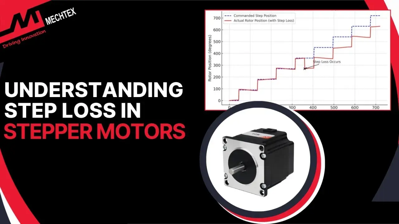
- Closed-loop control is now a practical option when missed steps are too expensive to ignore.
What a stepper motor is optimised for
A stepper motor is built for controlled incremental movement, not for the highest possible top speed. That is why I treat it as a positioning tool first and a rotating machine second. In motion-control work, its strengths are obvious: strong low-speed torque, predictable stepwise motion, and the ability to hold position when energised.
The important nuance is that the motor is only as useful as the load it can move without losing synchronism. Three torque terms matter here: holding torque, which is the static torque available at standstill; detent torque, which is the resistance you feel with no power applied; and pull-out torque, which is the real operating limit once the shaft is turning. If I am specifying a machine, I care far more about pull-out behaviour than about the biggest number in the brochure, because the machine fails in motion, not in a marketing table.
| Term | What it means | Why it matters |
|---|---|---|
| Holding torque | Torque available at rest while the coils are energised | Tells you whether the axis can stay put under load |
| Detent torque | Natural magnetic resistance with no current applied | Influences backdrivability and the feel of the mechanism |
| Pull-out torque | Maximum usable torque at a given speed before steps are lost | Defines the practical operating envelope |
That is the starting point. Once you understand what the motor is trying to achieve, the next question is how rotor and stator geometry create those properties in the first place.
The hardware choices that shape the motor
Most stepper motors used in industrial automation fall into one of three families: permanent magnet, variable reluctance, or hybrid. The hybrid type dominates modern motion control because it combines useful torque with fine step resolution. It is also the hardest to manufacture cleanly, which is why the geometry matters so much.
| Type | Strengths | Trade-offs | Typical use |
|---|---|---|---|
| Permanent magnet | Simple construction, moderate torque | Coarser step angle, lower precision | Low-cost devices and simpler mechanisms |
| Variable reluctance | Fast response, simple rotor | Lower torque and less common in modern systems | Specialist or legacy applications |
| Hybrid | Best mix of torque, resolution, and controllability | More complex rotor and stator manufacturing | Industrial motion control, automation, instrumentation |
The key physical choices are rotor tooth count, stator pole count, phase count, magnet strength, and winding layout. A standard hybrid design often uses 50 rotor teeth for a 1.8° step angle, or 200 steps per revolution. Doubling the rotor teeth to 100 can reduce that to 0.9°, which improves resolution, but the trade-off is not free: the magnetic structure becomes more demanding, tolerances tighten, and the torque per tooth can weaken if the design is pushed too far.
That same logic explains why five-phase motors are attractive in vibration-sensitive machines. With more phases and a smaller step angle, the motion becomes smoother, and the chance of audible resonance usually drops. In practice, I see this matter most in laboratory equipment, compact packaging machines, and other systems where noise is not just annoying but a sign that the mechanism is being excited too hard.
Once the geometry is set, the next challenge is deciding how much resolution is enough without sacrificing the torque you actually need.
How resolution and torque trade off against each other
It is tempting to chase the smallest possible step angle, but that is usually the wrong first move. Higher resolution helps when the machine needs very fine positioning, but each improvement comes with a cost somewhere else: more parts, more winding complexity, more sensitive tuning, or less torque headroom. In other words, resolution is useful only if the rest of the system can still do real work.
There are a few practical patterns I rely on. A 1.8° motor is still perfectly respectable for many axes when paired with a sensible driver and a decent mechanical transmission. A 0.9° motor gives more native resolution without making the design excessively specialised. A 0.72° motor or five-phase layout is worth considering when low vibration matters more than a marginal gain in simplicity. The point is not to choose the smallest number; it is to choose the best compromise for the load.
One detail that is easy to miss is that nominal step angle is not the same as usable accuracy. Well-made motors can hold a fine no-load step accuracy, but the actual machine outcome depends on backlash, coupling stiffness, bearing quality, and how the load behaves when acceleration starts. I always separate electrical resolution from mechanical accuracy, because confusing those two leads to optimistic specifications and disappointing prototypes.
That distinction becomes even more important once the driver enters the picture, because the driver can make the same motor behave very differently.
Why the driver and winding matter as much as the rotor
I never think of the driver as an add-on. It is part of the motor system. The same motor can feel tight, smooth, noisy, or unstable depending on how current is regulated and how the winding is matched to the supply. In motion control, the speed-torque curve is really a motor-driver curve, not a motor-only property.
Two electrical factors dominate performance: coil inductance and current control. High inductance slows the current rise at speed, which reduces usable torque unless the drive voltage and control strategy are chosen properly. That is why a motor that looks strong at low speed can run out of torque earlier than expected when the axis accelerates or the pulse rate climbs.
| Drive method | What it does | Best use | Main limit |
|---|---|---|---|
| Full-step | Moves in the largest discrete steps | Simple, robust control | More vibration and coarser motion |
| Half-step | Alternates between larger and smaller increments | Low-cost improvement in resolution | Uneven torque if not tuned carefully |
| Microstepping | Shapes phase current to divide each step into smaller increments | Smoother motion and lower resonance | Improves smoothness more than absolute accuracy |
| Closed-loop stepping | Uses feedback to confirm or correct position | Higher confidence under load variation | More cost and integration effort |
Microstepping is especially useful in modern machines because it reduces torque ripple and makes low-speed movement less jumpy. But I would not oversell it. It improves the shape of motion; it does not eliminate the effect of friction, backlash, or load spikes. If the mechanism is badly tuned, microstepping merely hides part of the problem.
For demanding automation systems, closed-loop control has become much more practical in 2026. It preserves the basic stepper architecture while adding the ability to detect and correct position loss, which is a good compromise when a missed move would stop production or damage a part. That leads naturally to the part most engineers feel in the machine itself: vibration.
How I keep vibration and missed steps under control
Most stepper problems are not caused by the motor alone. They come from the interaction between the motor, the driver, and the mechanics of the machine. Resonance is the classic issue: a particular speed band excites the system, vibration rises sharply, and the motor appears to lose smoothness or even skip. If I am tuning an axis, I look for those bands early instead of pretending they will disappear in production.
The practical fixes are straightforward, but they need discipline. I use acceleration ramps instead of abrupt starts, keep the load inertia in a sensible range, avoid flimsy couplings, and make sure the frame is stiff enough to stop the motor from shaking the whole assembly. Where the application allows it, a gearbox or belt reduction can make a big difference because it lets the motor operate in a friendlier part of its torque-speed range.
- Match inertia carefully. A load that is too heavy for the rotor will look fine at rest and fail once acceleration begins.
- Avoid harsh speed changes. Soft start and stop profiles reduce the chance of resonance.
- Keep wiring and current settings consistent. A poor current waveform can create noise that feels mechanical even though the cause is electrical.
- Use microstepping where smoothness matters. It is especially helpful for low-speed positioning and quieter machines.
- Test at real operating conditions. Heat, cable drag, lubrication, and load variation all matter more than a bench test suggests.
When the machine is noisy, my first instinct is not to blame the motor. I check the motion profile, the mounting stiffness, the current settings, and whether the mechanism has a resonance band that was never characterised. Only after that do I consider changing the motor family or moving to a closed-loop setup.
That testing mindset is what turns a theoretical design into something a production line can trust.
What I would lock down before signing off a design
If I were freezing a stepper-based motion axis for a real machine, I would verify the same small set of items every time. They are simple, but skipping them is how projects end up over-motored, under-damped, or impossible to tune after installation.
- Define the load torque, speed, acceleration, duty cycle, and environment before selecting the motor size.
- Choose the motor family and phase count based on the balance of resolution, noise, and manufacturing complexity.
- Match the winding, current rating, and supply voltage to the driver so the torque curve still makes sense at speed.
- Check mechanical details such as backlash, bearing quality, coupling stiffness, and frame rigidity.
- Validate the system with the worst-case load, not the easiest one on the bench.
That is the practical side of stepper work: the best design is rarely the one with the most exotic geometry. It is the one that produces stable motion, stays cool enough to run continuously, and behaves predictably when the machine gets real. If you treat the motor, driver, and mechanics as one system, the results are usually better and the debugging is far less painful.