Knowing how to wire a motor starter is really about separating the power path from the control path and matching both to the motor’s rating. In this guide I cover the parts you need to identify first, the safest order of work, the usual power and control circuit layouts, and the mistakes that typically cause trips, chatter, or a motor that refuses to run. I also show where a basic starter stops being the right tool and a drive makes more sense in motion control.
Key points to get right before energising the starter
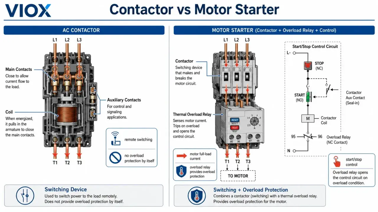
- A motor starter is usually a contactor plus overload protection; it is not a speed controller.
- The power circuit carries the motor current, while the control circuit decides when the coil energises.
- Safe isolation and proving dead are non-negotiable in UK work; live work needs a clear justification.
- The overload relay should be set to the motor nameplate current, not guessed.
- If you need speed variation, controlled ramps, or closed-loop motion, a VFD or servo drive is usually the better fit.
What a motor starter actually does in a motion control system
A starter’s job is simple but important: it connects the motor to the supply under control, then disconnects it when you stop, trip, or lose the run command. In practice, that usually means a contactor for switching and an overload relay for thermal protection, with upstream fuses or a breaker covering short-circuit protection. The starter protects the motor and the wiring, but it does not regulate speed the way a drive does.
That distinction matters in motion control. If the application is a conveyor, pump, fan, small machine tool, or a simple forward-reverse mechanism, a starter is often enough. If the process needs soft acceleration, variable speed, torque control, jogging, or position feedback, I would move away from a basic starter and look at a VFD or servo solution instead. A starter gives you on, off, and sometimes reverse; motion control often needs more than that.
Before you touch a terminal, the next step is to identify exactly what hardware you have and what voltages it expects.
The parts that must be identified before you land a cable
Most wiring mistakes start with assumptions. I prefer to check the starter and motor data first, then trace the wiring path on paper before I tighten a single screw.
| Item to confirm | What I check | Why it matters |
|---|---|---|
| Motor nameplate | Voltage, phase, full-load current, frequency, duty, and rotation direction | These values decide cable size, overload setting, and whether the starter is suitable |
| Starter type | Direct-on-line, reversing, star-delta, soft starter, or integrated starter | Each type has a different power path and control logic |
| Coil or control voltage | 24 V DC, 24 V AC, 110/120 V, 230 V, or another rated control supply | The coil must match the control circuit exactly or the contactor will not operate reliably |
| Overload relay | Adjustable range and trip class | The setting should match the motor nameplate current and the expected start profile |
| Protection upstream | Fuse type, breaker size, or motor-protective circuit breaker | The overload relay is not short-circuit protection |
| Auxiliary and safety devices | Start/stop buttons, emergency stop, interlocks, PLC output, or selector switch | These devices define the control circuit and the stop chain |
| Mechanical details | Enclosure rating, cable entry, earth bar, and terminal access | Poor termination and poor enclosure choice create faults that look like wiring errors |
Two details are easy to underestimate: the control voltage and the overload setting. I have seen perfectly good starters fail simply because the coil was specified for a different voltage, or because someone dialled in an overload value from memory instead of reading the motor plate. That is why the wiring sequence always starts with the diagram and the nameplate, not with the screwdriver.
Safe preparation under UK rules
In the UK, I treat motor starter wiring as dead-work by default. HSE guidance and the Electricity at Work Regulations 1989 make the expectation clear: isolate, lock off, prove dead, and only work live when it is genuinely unreasonable to make the conductor dead and suitable precautions are in place. A stop button is not an isolator, and a PLC command is not a safe state.
My practical sequence is straightforward:
- Isolate the supply at the correct point and lock it off.
- Prove the tester before and after checking the circuit.
- Verify absence of voltage on the incoming supply and, if relevant, on any control supply or stored-energy device.
- Check the motor shaft and driven machine are safe to move or test-bump.
- Confirm the panel has enough space, lighting, and access to work safely.
If the motor starter sits in a system with a VFD, brake module, or control transformer, I also check for stored energy and residual voltage. Capacitors can hold charge long after the supply is off, so I never assume the panel is safe just because the main disconnect is open. Once the installation is safe to touch, the actual wiring path becomes much easier to follow.
How the power circuit is normally wired
The power side is the heavy-current path from supply to motor. In a standard direct-on-line starter, the incoming supply lands on the line side of the contactor, usually marked L1, L2, and L3 on a three-phase device. The load side leaves the contactor, passes through the overload relay in most layouts, and then goes to the motor terminals. Protective earth goes directly to the starter earth point and the motor frame; it does not pass through the switching poles.That layout is easy to remember if you think in three blocks: isolation and protection upstream, switching in the middle, and motor protection before the load. The exact terminal numbers vary by manufacturer, so I always follow the diagram printed in the enclosure or the manufacturer’s manual rather than relying on habit. A good rule is to keep the power conductors short, neat, and mechanically secured with the correct glands, ferrules, and strain relief.
If the starter is reversing, the power circuit becomes slightly more complex. Two contactors are used, one for forward and one for reverse, and they must be mechanically and electrically interlocked so both cannot close at once. Reversal is achieved by swapping two phases, which changes motor direction. That is useful for conveyors, hoists, and simple actuator systems, but the interlock is not optional; without it, you risk a hard phase-to-phase fault the moment both contactors pull in.
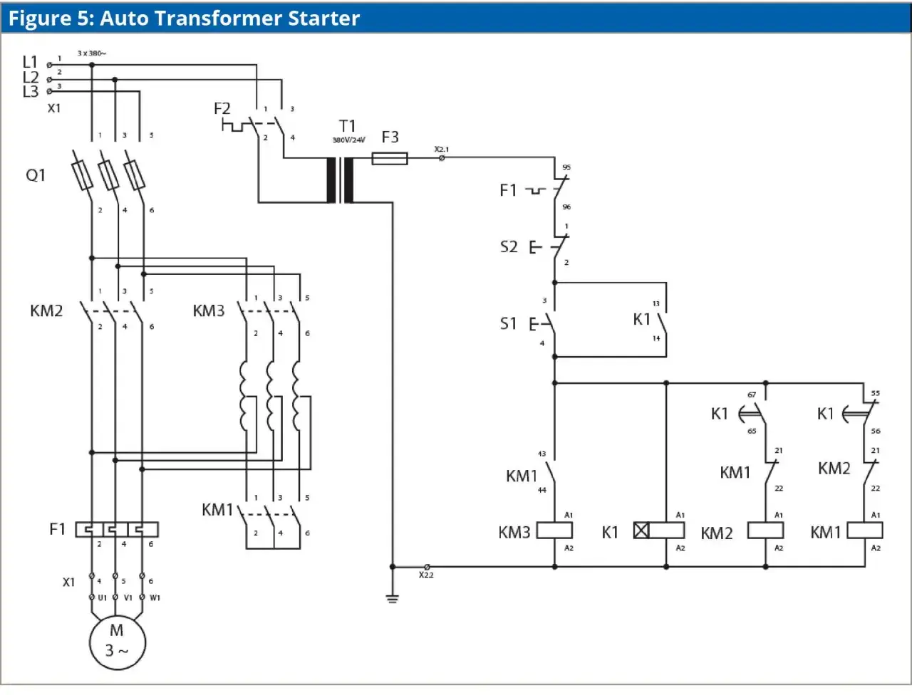
Star-delta and other reduced-voltage arrangements are different again. They use extra contactors and a different start sequence, so I would never wire one from memory or from a generic sketch. For anything beyond a basic direct-on-line or reversing starter, the safe approach is to follow the exact manufacturer schematic and confirm the motor is suitable for that starting method. The power side tells you where the current goes; the control side tells you when it is allowed to go there.
How the control circuit makes the starter start and stop
The control circuit is where most “it should work, but it doesn’t” problems live. It uses lower current to energise the coil, and it usually includes the stop device, overload auxiliary contact, start command, and a seal-in path that keeps the contactor energised after the start button is released. In a typical three-wire circuit, the stop pushbutton and the overload’s normally closed contact sit in series with the coil, while the start pushbutton is normally open and a normally open auxiliary contact bridges it once the contactor pulls in.
That auxiliary contact is often called the seal-in or holding contact. It is what turns a momentary pushbutton into sustained running without making the motor restart every time the button is released. If that contact is missing, miswired, or the wrong type, the starter may chatter, drop out, or fail to latch.
| Control style | How it behaves | Typical use | Watch-out |
|---|---|---|---|
| 2-wire maintained control | The starter follows a maintained contact or switch state | Floats, pressure switches, permissives, and simple automatic control | It can restart automatically after power returns if the input is still closed |
| 3-wire momentary control | A start pulse latches the coil through a seal-in contact | Local start/stop stations and manual operator control | Requires a correct stop chain and a working auxiliary contact |
In modern panels, I often see 24 V control circuits tied into a PLC or safety relay. That is fine, but the logic still needs to be clear: the run command should be separate from the safety stop chain, and the coil voltage must match the output stage or interposing relay. If the motor has an electromechanical brake or special run logic, I follow the dedicated brake or control diagram rather than forcing it into a generic starter pattern. Once the control logic is clear, the next question is whether a starter is actually the right device for the job.
When a basic starter is the wrong tool
A starter is binary equipment. It is good at starting, stopping, and sometimes reversing, but it does not give you speed control. That is the point where many motion applications move from a starter to a drive. I would use the comparison below as a quick reality check before I commit to a wiring strategy.
| Option | What it does | Best for | Wiring complexity |
|---|---|---|---|
| Direct-on-line starter | Applies full voltage to start and stop the motor | Pumps, fans, small conveyors, and simple loads | Low |
| Reversing starter | Starts the motor in either direction | Conveyors, actuator systems, and simple directional motion | Medium |
| Soft starter | Reduces starting stress and limits inrush | Loads that need gentler acceleration, not variable speed | Medium |
| VFD | Vary motor speed and often torque | Process control, speed regulation, and more refined motion control | Higher |
If the real requirement is speed variation, torque shaping, or controlled deceleration, I would not dress up a starter as a control solution. It will do the job badly, and the wiring will not rescue that limitation. The smarter move is to choose the device that matches the process. Even then, many faults still come down to basic wiring errors rather than the device itself.
Common mistakes that show up during commissioning
When a starter misbehaves, the symptom often points straight to the wiring mistake if you know what to look for. I keep a short mental list because these are the faults that waste the most time.
| Symptom | Likely cause | What I would inspect first |
|---|---|---|
| Contactor chatters or buzzes | Wrong coil voltage, weak control supply, or poor termination | Coil rating, control voltage, and terminal torque |
| Motor runs but trips quickly | Overload set too low, phase imbalance, or mechanical load too high | Motor current setting, line balance, and the driven machine |
| Starter will not latch | Missing or miswired seal-in contact | Auxiliary contact and start pushbutton wiring |
| Motor runs in the wrong direction | Phase order wrong or reversing circuit miswired | Motor phase sequence and interlock logic |
| Stop button has no effect | Stop contact bypassed or wrong contact type used | Series stop chain and any safety relay input |
| Control fuse keeps blowing | Coil short, wrong voltage, or a direct fault in the control circuit | Coil wiring, selector switches, and auxiliary contacts |
The two mistakes I see most often are line/load reversal and control-voltage mismatch. The first makes the current path look “almost” correct until the motor refuses to behave. The second can damage a coil or leave the starter in a permanent half-energised state. A reversed phase sequence is also easy to miss during first power-up, especially on pumps or conveyors where the process can tolerate motion only in one direction. That is why I always finish with a structured check before I hand the panel back.
The commissioning checks that save the most time later
I do not like treating commissioning as a quick power-on moment. A careful check takes a little longer, but it prevents the kind of fault that shows up an hour into production and then costs half a day to track down.
- Verify all terminations against the manufacturer diagram.
- Check torque on power and control terminals to the stated value.
- Confirm protective earth continuity to the starter and motor frame.
- Set the overload relay to the motor nameplate current.
- Test the stop chain, including any emergency stop or safety relay input.
- Confirm phase sequence and direction of rotation before coupling the load fully, if the process allows a brief bump test.
- Inspect cable routing, ferrules, glands, and enclosure sealing.
- Record the final settings and any abnormal observations.
On a UK installation, I also check that the work has been carried out in line with the site’s isolation procedure and the applicable electrical safety rules, because compliance is part of the job, not a separate administrative step. If the starter is part of a machine with braking, interlocked guards, or a VFD upstream or downstream, I test those functions separately instead of assuming they behave like a plain motor circuit. The best wiring job is the one that is easy to inspect, easy to maintain, and unsurprising when the machine is started for the first time.