Most IEC motor starters use a contactor, an overload device, and some form of short-circuit protection; the exact mix changes with the duty cycle, the panel space available, and how much control the machine needs. In motion-control work, that matters because the starter is not only switching power, it is shaping how a motor starts, stops, reverses, and reports faults. I will keep this practical: what is usually inside the starter, which technologies are common, and how I would choose between them for a UK industrial panel.
The short version for busy engineers
- The core IEC starter set is still contactor plus overload protection plus short-circuit protection.
- Thermal overload relays remain common for standard fixed-speed duty, while electronic relays add better diagnostics.
- Soft starters are used when the load needs a gentler ramp, not when it needs variable speed.
- Reversing and star-delta arrangements appear when direction change or reduced starting current is part of the job.
- UK panel choices are usually driven by 400/415 V supply practice, control voltage, coordination, and enclosure space.
What an IEC motor starter really does
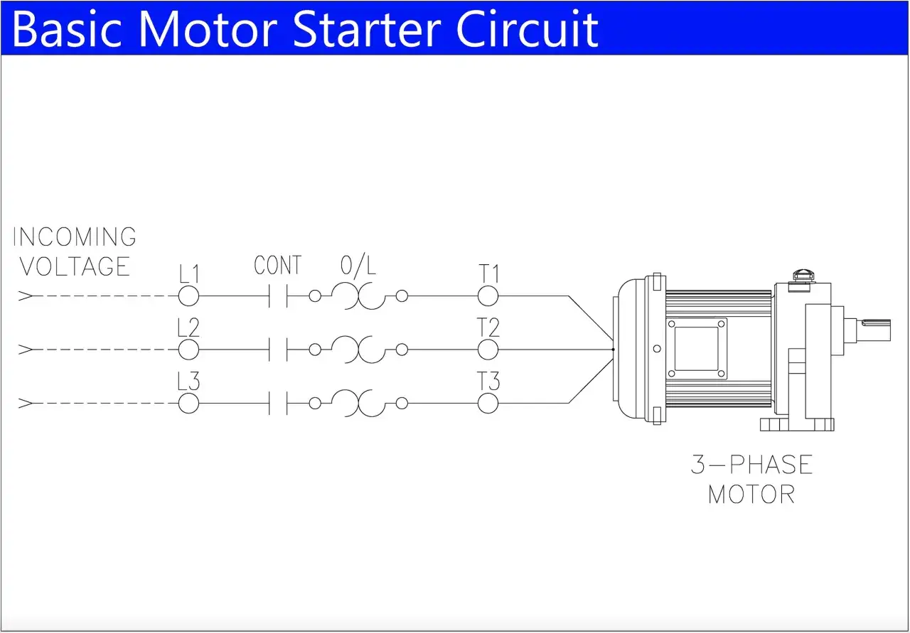
I usually reduce an IEC starter to three jobs: switch the motor cleanly, protect it properly, and let the control system command it safely. Schneider Electric describes a motor starter in exactly that spirit, as a combination of electromechanical devices that connects the motor to its supply while handling on/off control and protection against overloads, short circuits, phase loss, and other faults.
That definition matters because people often treat the starter as a single part. In reality, it is a coordinated set of functions. The contactor does the switching, the overload device watches sustained current, and the upstream protection element deals with fault current fast enough to stop damage. If the application needs reversing, soft starting, or a local control station, those functions are layered on top rather than replacing the basics.
For motion control, the boundary is important. A starter is ideal for fixed-speed motors that need start, stop, reverse, and protection. Once the process needs actual speed regulation or torque shaping across a range, I stop thinking in starter terms and start thinking in drive terms. That distinction saves bad specifications later, because a starter can do a lot, but it is not a variable-speed controller.Once that role is clear, the next question is what shows up inside the panel most often and why those parts are still the default choice.
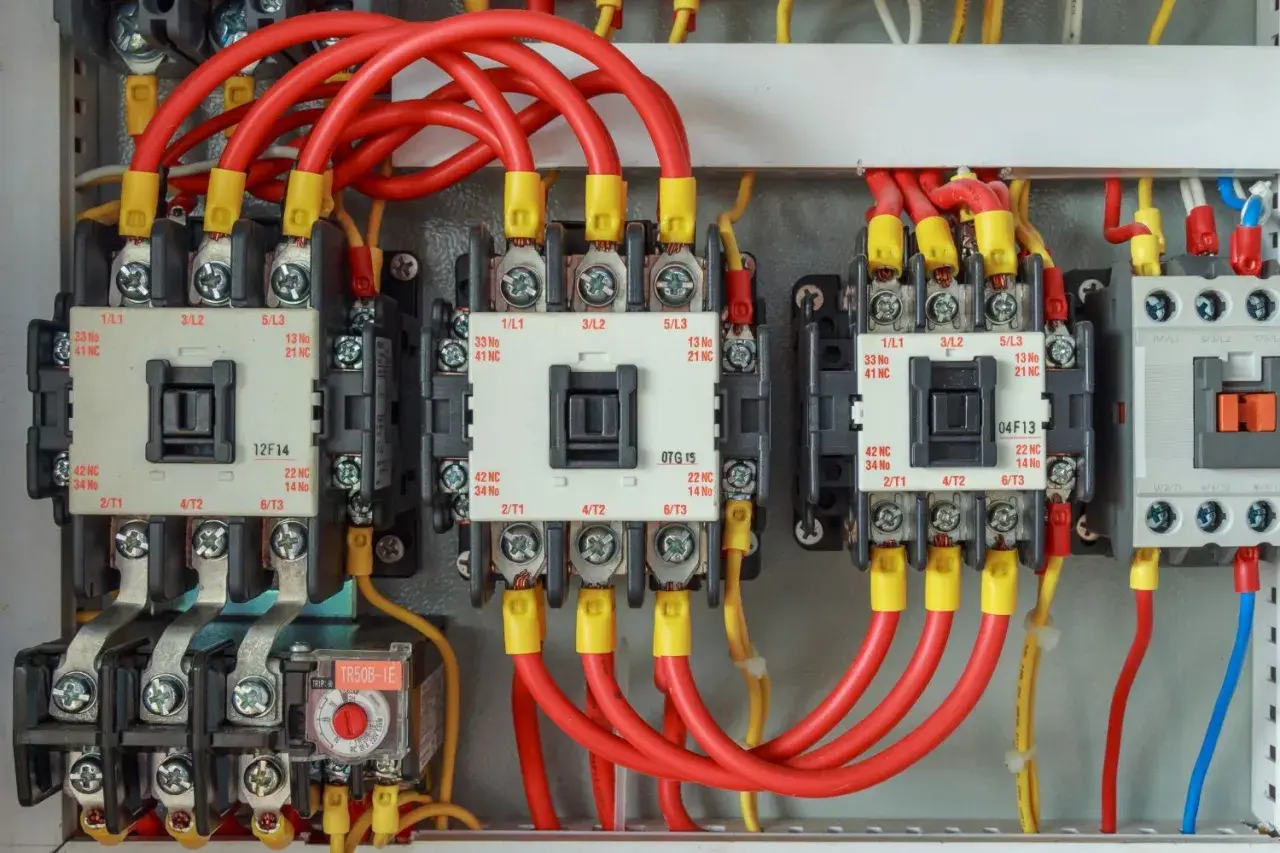
The parts I see in most starter panels
| Component | What it usually is | Why it is used |
|---|---|---|
| Contactor | 3-pole electromagnetic contactor, commonly sized for IEC motor duty such as AC-3 | Lets the PLC, push buttons, or relay logic switch the motor remotely and repeatedly |
| Overload relay | Thermal bimetal relay or electronic overload relay | Protects against sustained overload, phase loss, and thermal stress |
| Short-circuit protection | Motor protection circuit-breaker, MCCB, or fuses | Clears faults fast enough to protect cables, contactors, and the motor feeder |
| Auxiliary contacts | Feedback contacts mounted on the contactor or relay | Give interlocks, status feedback, and permissive signals back to the control system |
| Control device | Push buttons, selector switches, pilot lights, PLC outputs, or IO-Link signals | Provides local and remote control, plus basic state indication |
| Accessories | Mechanical interlocks, surge suppressors, timers, control transformers | Supports reversing logic, reduces coil noise, and adapts the starter to the control architecture |
I also look closely at the control side. In a modern panel, a 24 V DC control circuit is often easier to integrate with PLCs and safety architecture than a legacy higher-voltage coil arrangement, and a coil suppressor is not optional if you care about noise and output life. Those small decisions are rarely glamorous, but they are usually where commissioning time is won or lost.
With the hardware map in place, the next choice is which protection technology is actually the right fit for the job.
Which protection technology fits which job
| Technology | Best fit | Main strength | Main limitation |
|---|---|---|---|
| Thermal overload relay | Standard pumps, fans, conveyors, and general fixed-speed loads | Simple, familiar, compact, and cost-effective | Limited diagnostics and less visibility into what caused the trip |
| Electronic overload relay | Panels where phase imbalance, remote reset, or trip data matter | Better adjustability and clearer fault information | Higher cost and slightly more setup effort |
| Motor protection circuit-breaker | Compact starter packages that need integrated short-circuit and overload protection | Combines protection functions neatly in one device | Less flexible if the control philosophy is highly customised |
| Advanced motor protection relay | Critical processes, larger motors, or applications with more fault modes to watch | Adds phase failure, underload, jam, voltage, and communication features | Requires more disciplined engineering and commissioning |
| Fused disconnect arrangement | Installations that want very clear fault separation and strong coordination | Fast fault interruption and well-understood behaviour | More parts to coordinate and maintain |
For ordinary duty, I still see thermal devices doing the bulk of the work because they are robust and easy to understand. For more demanding panels, electronic relays earn their keep fast, not because they are trendy, but because they tell you more about what happened. That visibility becomes especially useful when the starter sits inside a larger automation system and the maintenance team needs more than a red lamp.
There is also a practical coordination angle here. Eaton’s IEC guidance, for example, shows how motor starters are paired with fuses or circuit-breakers to achieve defined coordination levels. That is the sort of detail people skip during design and then regret when a fault takes out more hardware than expected.
Those protection choices become even more important when the starter has to behave well inside a motion system, especially when starting torque, direction changes, or mechanical stress are part of the picture.
Where soft starters and reversing circuits matter in motion control
Soft starters sit in a useful middle ground. They are not speed drives, but they are good at controlling how a motor gets up to speed and how it comes back down. In motion-control terms, that matters on pumps, fans, compressors, conveyors, and other loads that punish abrupt starts with belt shock, mechanical wear, or supply dips. Siemens and Eaton both frame soft starters this way: they reduce stress by managing acceleration and deceleration rather than slamming the motor straight to full voltage.
That is why I treat soft starters as a mechanical and electrical smoothing tool, not as a universal upgrade. If the process needs actual closed-loop speed control, I would move to a variable frequency drive rather than forcing a starter to do a job it was never meant to do. The difference is simple: a starter changes how the motor starts; a drive changes how the motor runs.
Read Also: What is a Stator? The Unsung Hero of Motion Control
Common starter arrangements in motion applications
- Direct-on-line starters suit simple fixed-speed machines where the inrush current is acceptable and the mechanics are forgiving.
- Reversing starters add interlocked contactors so the motor can change direction safely, which is useful on conveyors, feeders, and some handling equipment.
- Star-delta starters still have a place on some larger motors when the load can tolerate the transition and reduced starting current is worth the extra complexity.
- Soft starters are my first choice when the issue is torque shock, voltage dip, or a fragile mechanical train.
- Compact combination starters help when panel space, wiring time, and standardisation matter more than bespoke architecture.
In practice, the starter type is often chosen by what the machine can tolerate rather than by what the motor can technically survive. A conveyor that needs a gentle ramp is a different problem from a fan that just needs clean on/off control, and a reversing feeder is a different problem again. Once you separate those cases, the selection process becomes much cleaner.
From there, the final step is turning the theory into a panel choice that makes sense in a UK installation.
How I would choose one for a UK installation
For a typical UK industrial panel, I start with the motor nameplate and the actual start profile, not with horsepower on a brochure. The local supply is usually 400/415 V three-phase, so the real questions are motor full-load current, starting frequency, control voltage, space, and how much fault tolerance the process needs.| Decision point | What I check first | What it usually leads me toward |
|---|---|---|
| Motor duty | Fixed speed, reversing, star-delta, soft start, or frequent jogging | DOL starter, reversing starter, or soft starter package |
| Coordination | How much damage is acceptable after a short circuit | Type 1, Type 2, or a more protective fused arrangement |
| Control architecture | 24 V DC PLC outputs, legacy AC coils, or mixed control | Electronic relay, coil suppression, and clear auxiliary feedback |
| Diagnostics | Does maintenance need trip codes, current data, or remote reset? | Electronic overload or an advanced motor protection relay |
| Panel constraints | Space, heat, cable routing, and ease of servicing | Compact starter, modular components, or a preassembled combination starter |
| Environment | Temperature, dust, vibration, and enclosure rating | Rugged enclosure and accessories that match the site conditions |
I also pay attention to how the panel will be maintained. If a maintenance technician can replace or diagnose a device quickly, the design is better. If a fault forces them to infer everything from a tripped breaker and a vague lamp, the design is already weaker than it looked on the drawing. That is why compact starters with clean feedback and sensible labelling tend to age better than overcomplicated builds.
The last thing I would do is let the wrong assumptions creep in during commissioning, because most bad starter jobs are not caused by the motor itself.
The mistakes that cause nuisance trips and weak protection
- Undersizing the contactor for the real duty. A motor that starts heavily or reverses often needs more than a basic sizing rule of thumb.
- Setting the overload relay too tightly. That usually turns a healthy load into a nuisance-trip machine, especially on warm days or after repeated starts.
- Ignoring phase loss or imbalance. A motor can limp along long enough to overheat if the protection is too simple.
- Using a soft starter as if it were a speed controller. It will smooth the start, but it will not give you real speed regulation.
- Skipping interlocks on reversing circuits. That is a direct path to stress, faults, and avoidable downtime.
- Mixing control voltages without a plan. PLC outputs, coil ratings, and auxiliary feedback must all agree, or commissioning becomes messy fast.
- Choosing protection only on price. A slightly better coordinated starter often pays for itself the first time a fault stays local instead of cascading through the panel.
I see one recurring pattern behind almost all of these mistakes: the starter is chosen as a part, not as a system. Once you think in terms of contactor, overload, short-circuit protection, controls, and maintenance as one package, most of the common failures become easier to avoid.
The starter package I would standardise first
If I were standardising a modern motion-control panel, I would start with a compact IEC starter built around a properly rated contactor, a correctly set overload device, and coordinated short-circuit protection. For many fixed-speed machines, that remains the cleanest, most serviceable option. If diagnostics matter, I would move up to an electronic overload or motor protection relay. If the load needs a gentler start or stop, I would add a soft starter rather than trying to force the base starter to do everything.
That is the line I use in practice: keep the starter simple when the machine is simple, and add intelligence only when it buys you uptime, smoother motion, or better fault visibility. That approach is usually more reliable than chasing the fanciest device on the market, and it tends to leave maintenance teams with a panel they can actually trust.
For most IEC motor starters, the answer is still a disciplined mix of contactor, overload protection, and coordinated fault interruption, with soft-start or digital features added only when the application genuinely needs them.