The practical side of 3 phase motor connections comes down to matching the winding pattern to the supply, the nameplate, and the load. In the UK, that usually means a 400V three-phase system, so the difference between star and delta matters immediately on pumps, fans, conveyors, and other motion-control machines. I’ll walk through the terminal markings, the wiring patterns, the start-method choices, and the checks that keep the first run uneventful.
What matters most before wiring a three-phase motor
- Read the nameplate first. A 230/400V motor usually runs in star on a 400V supply, while a 400/690V motor usually runs in delta on 400V.
- Most IEC motors use six terminals. U1, V1, W1 and U2, V2, W2 tell you how the windings are brought out for linking.
- Star reduces current and torque. It is useful for easier starting, but it is not a speed-control method.
- Delta gives full winding voltage. It is the right running arrangement only when the motor is designed for it at the supply voltage.
- Earth the frame and check rotation. Neutral is usually not used on the motor itself, but protective earth always is.
- For motion control, a VFD gives the best control. Star-delta helps with starting; it does not replace proper speed and ramp control.
Start with the nameplate, not the diagram in your head
When I open a motor terminal box, the first thing I want is the nameplate. That label tells me whether the machine is built for 230/400V, 400/690V, or a single fixed voltage, and that decides the correct connection before any links move. On a UK 400V supply, a 230/400V motor normally runs in star, while a 400/690V motor normally runs in delta.
That detail matters because the winding does not care what the supply cable is called; it only cares about the voltage across each coil. If the motor is mislinked, it may still spin, but it will run hot, pull the wrong current, or trip protection long before anyone calls it “healthy”.
| Nameplate marking | What it means | Usual connection on a UK 400V supply |
|---|---|---|
| 230/400V, Δ230/Y400 | Lower voltage in delta, higher voltage in star | Star |
| 400/690V, Δ400/Y690 | Lower voltage in delta, higher voltage in star | Delta |
| 400V only or fixed-voltage marking | Usually not intended for re-linking between star and delta | Follow the fixed diagram on the motor or inside the cover |
If the plate also gives current values, I use the current that matches the actual connection, not a generic figure from the starter or drive. That is the number the overload protection should be built around, and it is one of the easiest places to avoid nuisance trips. Once the rating is clear, the next job is to read the terminal box correctly.
Read the terminal box markings before you move a single link
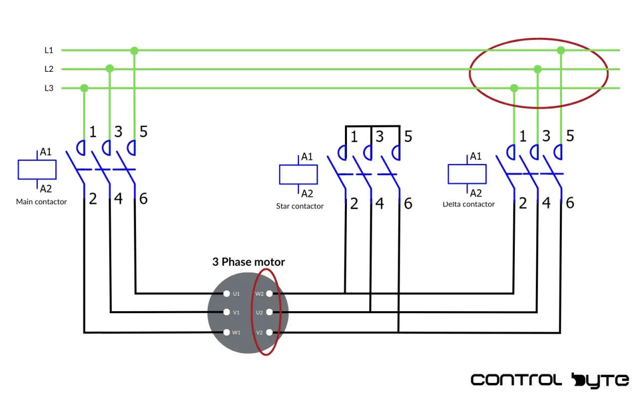
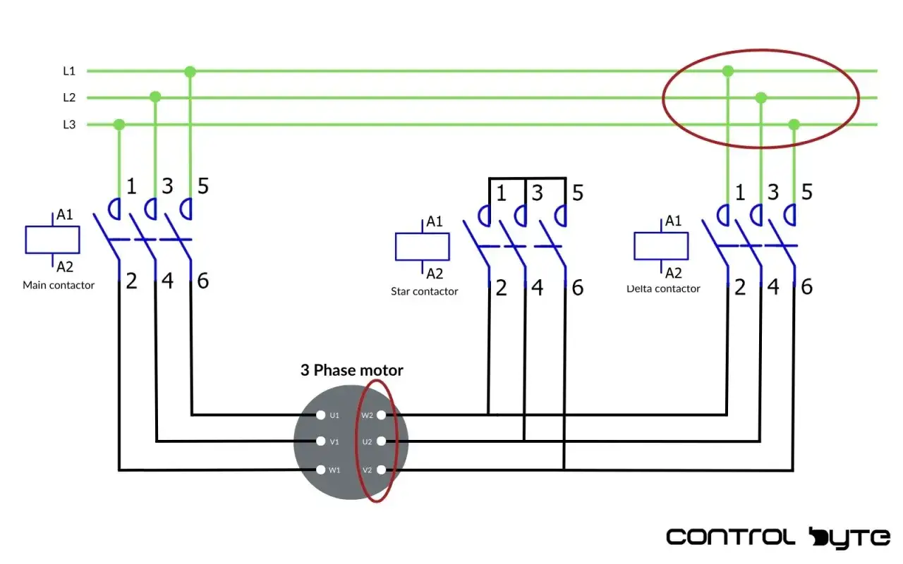
Most IEC motors bring out six terminals: U1, V1, W1 are one end of the three windings, and U2, V2, W2 are the other ends. The link pattern decides whether those windings sit in star or delta, and the physical layout inside the box can vary by manufacturer, so the cover diagram always wins if it conflicts with memory.
I also check the protective earth point before anything else. Three-phase motors normally do not use a neutral conductor at the motor itself, but the frame must be bonded properly to PE. That is not a formality; it is the difference between a safe fault path and a live casing.
| Connection | Link pattern in the terminal box | How the supply lands | Typical use |
|---|---|---|---|
| Star (Y) | Join U2, V2, and W2 together | L1 to U1, L2 to V1, L3 to W1 | 230/400V motor on a 400V supply, or any case where reduced start current is needed |
| Delta (Δ) | Bridge U2 to V1, V2 to W1, and W2 to U1 | The three line conductors land on the three junctions created by those bridges | 400/690V motor on a 400V supply, or 230/400V motor on a 230V three-phase supply |
The important part is not the drawing style but the electrical relationship between the terminals. I have seen perfectly good motors wired wrongly because someone copied the link orientation from a different terminal block and assumed the physical shape mattered more than the labels. It does not. The labels do.
How star and delta change the way the motor behaves
Star and delta are not just two ways to shuffle links. They change the voltage across each winding, and that changes the starting current, starting torque, and the way the machine feels when it first moves. On a 400V system, star puts about 230V across each winding, because the phase voltage is reduced by the square-root-of-three relationship.
That reduction is useful, but it comes with a cost. As a rule of thumb, star-delta starting reduces starting current to around 2 to 2.5 times rated current, compared with roughly 7 to 8 times rated current for direct-on-line starting. Starting torque also drops to about one third, which is why the load matters so much.
| Pattern | Voltage across each winding on a 400V supply | What I expect at start-up | Best fit |
|---|---|---|---|
| Star | About 230V per winding | Lower inrush, softer acceleration, lower torque | Fans, light pumps, and other loads that do not need much breakaway torque |
| Delta | Full 400V per winding | Stronger start, higher current draw | Running condition for motors designed for 400V delta operation |
That is why star-delta starting is common on certain industrial loads and a poor fit on others. A centrifugal fan usually tolerates reduced start torque quite happily. A heavily loaded conveyor, crusher, or positive-displacement pump often does not. If the machine needs true speed control or controlled acceleration profiles, I would not treat star-delta as a substitute for a drive.
A wiring sequence that avoids most field errors
My sequence is simple, and I do not improvise much on it. The people who get into trouble usually skip one of these checks and then try to reason backwards from a tripping overload or a motor that spins the wrong way.
- Isolate the supply, lock it off, and prove dead.
- Read the nameplate and the terminal-box diagram together.
- Choose the correct link pattern for the actual supply voltage.
- Fit the links firmly and confirm there are no crossed bridges.
- Connect L1, L2, and L3 to the correct terminals, then connect PE to the frame.
- Tighten the terminals to the manufacturer’s specified torque and secure the gland so the cable cannot move.
- Check insulation and phase rotation before coupling the machine to its load, or before running it hard if the load is already connected.
If the motor is on a drive, I also follow the drive manufacturer’s test procedure. Some inverter-fed motors need the drive isolated before insulation testing, and the EMC arrangement for the cable screen is not something I guess at. In motion-control work, the wiring and the drive settings need to agree with each other; otherwise the first start can look like an electrical fault when it is really a setup mismatch.
Choose the starting method that matches the motion task
This is where the conversation often gets muddled. Star-delta, direct-on-line, and a VFD all solve different problems. If the machine only needs to start and then run at fixed speed, a simpler starter may be enough. If it needs speed variation, soft ramping, or repeatable motion profiles, I would move straight to a variable-frequency drive.
| Method | What it gives you | Best fit | Main trade-off |
|---|---|---|---|
| Direct-on-line | Simple wiring and full starting torque | Smaller motors and loads that can handle the inrush | Highest starting current |
| Star-delta | Reduced starting current | Larger motors with light or moderate starting loads | Lower starting torque and more switching gear |
| VFD | Controlled speed, acceleration, and deceleration | Conveyors, mixers, process lines, and motion-control systems | Higher upfront cost and more setup detail |
One point I always make clear: star-delta is a starting method, not a speed-control method. It can ease mechanical stress at start-up, but it does not give you the process flexibility that a drive does. In a motion-control context, that difference is usually the deciding factor.
The mistakes that create trips, heat, and wrong rotation
Most motor problems I see after a connection change are not dramatic faults. They are small wiring errors that compound under load. The motor may hum, stall, trip on overload, or run in the wrong direction, and the root cause is often obvious once the box is opened again.
- Using the wrong nameplate logic. A 230/400V motor on a 400V supply belongs in star, not delta. A 400/690V motor on 400V belongs in delta, not star.
- Leaving a link loose. A poor bridge connection creates heat and intermittent faults that are hard to trace.
- Assuming wire colour tells the whole story. Colours help, but terminal labels and rotation checks matter more.
- Starting a high-torque load in star. The motor may not develop enough torque to accelerate cleanly, so current stays high and the starter can trip.
- Ignoring overload settings. Protection should match the actual motor current in the actual connection, not an estimate from memory.
- Swapping phases without checking the machine. Reversing direction is easy electrically, but the driven mechanism may not tolerate reverse rotation.
When a motor starts badly, I resist the urge to “try it once more”. That usually makes the electrical and mechanical stress worse. A clean wiring check is quicker than chasing a damaged coupling, a hot winding, or a repeated overload trip.
The last checks I make before the first live run
Right before energising the circuit, I want five things confirmed: the earth is sound, the links match the nameplate, the terminals are tight, the load can move safely, and the phase rotation is correct. If the motor is coupled to a gearbox, pump, or conveyor, I want to know whether the machine can start unloaded or whether a controlled first start is safer.
- Confirm PE continuity to the motor frame and enclosure.
- Verify the final link arrangement against the cover diagram.
- Check overload and protection settings against the actual motor current.
- Test rotation with the load clear, if that is possible and safe.
- For a VFD, confirm volts, amps, frequency, acceleration, and deceleration settings before the first run.
When those checks are done properly, the first start is usually quiet and predictable, which is exactly what I want from an industrial motor. The real goal is not simply to make it turn; it is to make it turn in the right direction, at the right current, and without wasting the machine’s mechanical life on avoidable stress.