A Variable Frequency Drive does more than change motor speed. It reshapes the power feeding the motor, and that means voltage, frequency, torque, and heat all interact in ways that matter for real motion control work. In this article I break down what actually happens inside the drive, how to read the output correctly, and where the common misunderstandings start.
What matters most when a VFD is changing motor power
- The drive changes voltage and frequency together, not just speed.
- The output is usually a PWM waveform, so it is not a clean sine wave like the mains supply.
- Below base speed, voltage is normally reduced with frequency to keep motor flux under control.
- At and above base speed, the output voltage usually tops out at the drive’s available limit.
- A weak reading on a basic multimeter does not always mean the drive is wrong; the waveform itself can confuse the meter.
- For motion control, the important question is not only “does it change voltage?” but “does it deliver the right voltage for the operating point?”
What a VFD changes in the power chain
The simplest answer is yes: a VFD changes the voltage that reaches the motor. But it does not do that in the same way a transformer does. In the usual drive architecture, the incoming AC supply is rectified into DC, then the inverter section rebuilds that into a controlled AC output. ABB describes that inverter stage as producing a variable AC voltage and frequency output, which is the key point most people miss.
That means the drive is not just “passing through” mains power. It is actively regulating how much energy reaches the motor, and it does so by controlling the output waveform. On a standard UK industrial system, that is often the difference between a motor that runs safely at the required torque and one that wastes energy, overheats, or never reaches the performance the process needs.
| Stage | What happens | Why it matters |
|---|---|---|
| Mains input | Fixed AC supply enters the drive | This is the source voltage, usually unchanged at the input terminals |
| Rectifier and DC link | AC is converted to DC and smoothed | The drive builds an internal energy reserve for the inverter |
| Inverter output | IGBTs switch the DC into controlled AC pulses | This is where the drive changes both frequency and effective voltage |
I like to think of this stage-by-stage view as the cleanest way to explain the answer. The drive is not a simple voltage reducer or booster; it is an electronic power controller. That distinction becomes much clearer once you look at the output waveform itself.
How the output voltage is actually controlled
The output from a VFD is usually a pulse-width modulated waveform, not a perfect sine wave. ABB’s technical material makes this point directly: the drive output is built from voltage pulses, and the longer the switch stays on, the higher the output voltage becomes. In practice, the drive varies the pulse pattern to produce the effective voltage the motor needs at that speed.
That is why the phrase “does a VFD change voltage” is a little too simple on its own. The drive changes the apparent or effective voltage, and it does so in step with frequency. At low speeds, it usually reduces voltage so the motor does not draw excessive magnetising current. At higher speeds, it raises voltage until it reaches the drive’s available limit.
Below base speed
In the normal operating region, the drive keeps the voltage-to-frequency relationship roughly proportional. This is often called V/Hz control. The goal is to hold the motor flux in a usable range so the motor can produce torque without overheating. On a 400 V, 50 Hz motor, that often means the drive is shaping the output so the motor sees less voltage when it is commanded to run at less than 50 Hz.
Read Also: VFD Output Reactors - When to Use Them (or Not)
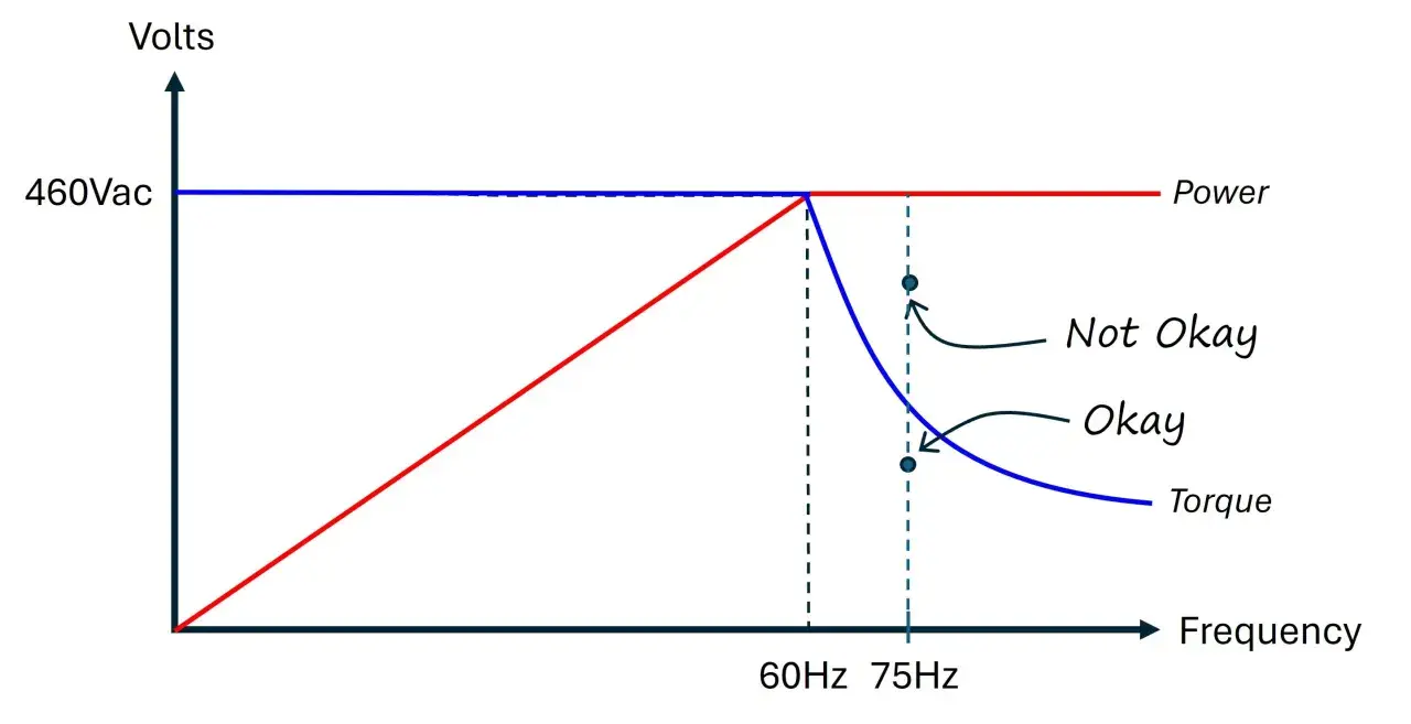
Above base speed
Once the drive reaches base frequency, the output voltage usually cannot climb indefinitely. At that point the motor enters field weakening, which means speed can increase, but available torque drops. Danfoss documentation notes that above the field-weakening point the output voltage remains at the set maximum value. That is the practical ceiling most operators run into.
For motion systems, that behaviour is not a footnote. It is the difference between a conveyor that accelerates cleanly and a spindle that runs out of torque the moment the speed command pushes past the useful range. That leads straight into the performance side of the story.
What that means for torque, speed, and heat
The point of changing voltage is not voltage itself. It is motor control. If the drive lowers voltage in the right proportion to frequency, the motor can keep producing the torque the application needs. If the voltage is too low at a given speed, the motor compensates by drawing more current, which raises heat and shortens insulation life over time.
ABB’s guidance is useful here: many VFDs aim to provide motor nameplate voltage at full speed. That is exactly what you want in a properly matched drive-and-motor pair. At rated speed, the motor expects the voltage it was designed for, and if it does not get it, torque margin disappears quickly.- Good voltage matching helps the motor hold torque without excess current.
- Too little voltage at full speed usually shows up as overheating, poor acceleration, or current alarms.
- Too much expectation from the drive is a common mistake; a standard VFD cannot create unlimited voltage.
- Load type matters; fans and pumps tolerate voltage changes differently from constant-torque conveyors or indexing axes.
For motion control, I usually separate the question into two layers: can the drive run the motor, and can it run it well enough for the process? That distinction matters most when the system is loaded hard or when speed accuracy becomes important.
When the drive cannot raise voltage any further
A standard VFD is limited by its DC bus and the topology of the power stage. If the supply is fixed, the output ceiling is fixed too. In other words, the drive can shape voltage, but it cannot normally exceed the available internal voltage reserve. Some advanced topologies behave differently, but the everyday industrial answer is still the same: a drive is constrained by what the front end can provide.
This is why “voltage boost” claims can be misleading unless you look closely at the hardware. If you feed a drive with a lower-class supply, the motor output class is usually limited accordingly. A drive on a 230 V input system does not magically become a 400 V source for a 400 V motor. It must stay within the electrical limits of the platform.
There is one more subtle point worth keeping in mind. If the incoming line sags, the drive may lose output headroom unless it has a design that supports better ride-through or voltage maintenance. That is why the supply side, not just the motor side, matters when you are sizing a system for repeatable motion.
How I would check the output on site
If I needed to verify what a VFD is doing in a real installation, I would not start with a basic handheld meter and assume the reading is meaningful. The PWM waveform can fool standard meters. I would check the drive display or parameters first, then confirm with the right measuring tool if needed.
- Check the drive’s commanded frequency and output voltage parameters.
- Confirm the motor nameplate voltage, frequency, and current.
- Use a true-RMS meter rated for VFD work if you need a field reading.
- For waveform detail, use an oscilloscope or power analyser designed for inverter outputs.
- Compare the result against the operating region, especially below base speed and at full speed.
The reason I stress this is simple: a meter that is happy on clean mains power may give you a number that looks wrong on a VFD output, even when the drive is behaving normally. Once you know that, the next step is avoiding the mistakes that create those false alarms in the first place.
Common mistakes that distort the answer
The most common mistake is assuming the output should look like the input. It should not. A VFD output is intentionally different. The second mistake is treating the drive as a universal voltage converter. It is not; it is a controlled inverter with limits.
- Using a non-VFD meter and trusting the displayed voltage too much.
- Expecting the drive to raise voltage above its available bus level.
- Ignoring motor cable length, which can increase reflected-voltage stress and dv/dt problems.
- Running a motor that is poorly matched to the drive class or supply class.
- Assuming low-speed performance will be identical across V/Hz and vector-control modes.
In my experience, cable length and filtering are the two issues people underestimate most often. If the motor is far from the drive, the waveform at the motor terminals can be harsher than the number shown at the drive, and that matters when insulation stress or bearing wear starts showing up. That is the practical side of the question, and it leads directly to the final takeaway.
What this means for motion control projects
The clean answer is that a VFD does change voltage, but it does so as part of a larger control strategy. It adjusts voltage and frequency together so the motor can deliver the speed and torque the process needs. If you only ask whether the voltage changes, you miss the more important question: does it change correctly for the load, the motor, and the control mode?
For most motion control applications, I would check three things first: the motor nameplate match, the base-speed behaviour, and whether the output waveform needs filtering or better measurement. Get those right, and the drive is usually straightforward to work with. Get them wrong, and the symptoms often look like a drive fault when the real issue is an electrical mismatch.
The best rule of thumb is this: a VFD is not just a speed knob. It is an electronic power stage that reshapes voltage to control motion, and that is exactly why it is so useful in industrial automation.