The stator is the fixed electromagnetic half that makes rotation useful
- It is the non-moving part of a motor or generator, usually built around a laminated steel core and copper windings.
- In a motor, it creates the magnetic field that drives the rotor; in a generator, it is where output voltage is taken from.
- Its design affects torque, speed smoothness, heat, noise, efficiency, and positioning accuracy.
- In motion control, the stator works with the drive to produce precise current changes and fast response.
- Most problems show up as heat, insulation ageing, contamination, vibration, or uneven air gap behaviour.
- Good performance depends on the right winding design, cooling, and insulation class for the duty cycle.
What the stator actually does
I usually describe the stator as the part that does the electrical heavy lifting without moving. It sits in the machine frame, carries the windings, and establishes the magnetic field that interacts with the rotor. That interaction is what turns electrical energy into mechanical motion in a motor, or mechanical motion into electrical energy in a generator.
Stationary does not mean passive. The stator is where a lot of the real work happens. Its windings carry current, its iron core guides flux, and its insulation system has to survive heat, vibration, and repeated electrical stress. In many industrial machines, the stator is also the main limit on how hard the machine can be pushed for long periods.
In motors, the stator is part of the magnetic circuit. In generators, it is the place where the produced voltage is collected and delivered to the load or grid. That is why the same word shows up across drives, generators, servo systems, and industrial automation: the stator is the fixed reference point that makes the rotary machine behave predictably. Once that role is clear, the next step is to see how it cooperates with the rotor.
How the stator and rotor create motion
The rotor is the moving part, but it cannot do useful work without the field created by the stator. In an induction motor, alternating current in the stator windings creates a rotating magnetic field. The rotor follows that field with a small speed difference called slip, and that difference is what produces torque.
For a four-pole machine on a 50 Hz supply, the theoretical synchronous speed is 1,500 rpm. In practice, an induction motor runs a little below that because it needs slip to develop torque. That detail matters in the UK, where many industrial systems still operate on 50 Hz power and engineers need to think in terms of actual machine behaviour, not just nameplate numbers.
| Part | Motor role | Generator role |
|---|---|---|
| Stator | Creates the magnetic field that drives the rotor | Receives the induced output voltage in the windings |
| Rotor | Responds to the stator field and turns the shaft | Provides the moving magnetic field or mechanical input |
| Air gap | Small space where flux transfers energy efficiently | Small space where the magnetic field induces output |
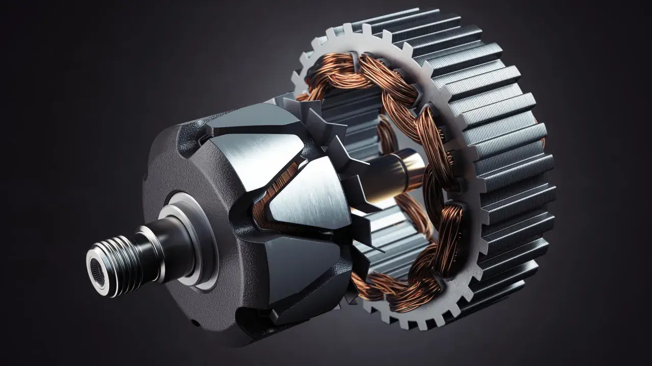
Inside the stator assembly
A stator is not a single block of metal. It is an assembly made up of a frame, a laminated core, slots, windings, insulation, and often cooling features that keep the machine within its thermal limits. The exact design varies by motor type, but the basic structure is the same across most industrial machines.
The core and laminations
The core is usually built from stacked steel laminations rather than one solid piece. That is done to reduce eddy-current losses and keep heating under control. In other words, the metal is shaped to guide the magnetic field efficiently without wasting too much energy as heat. A good stator core is one reason industrial motors can run for long periods without falling apart thermally.
The windings
The windings are the copper conductors that carry current through the stator. Their geometry controls how the magnetic field is formed, how smoothly torque is produced, and how much resistance the machine has in operation. More resistance means more I²R loss, which is simply heat created when current flows through the winding. This is one reason wire size, fill factor, and winding layout matter so much in real equipment.
Cooling and the frame
The frame supports the stator mechanically and helps transfer heat away from the core and windings. In smaller motors, cooling is usually air-based. In larger generators and some high-duty industrial machines, the stator may use more advanced cooling paths, including forced air or even water-cooled windings in specialised designs. The cooling system is not an accessory; it is part of the stator’s performance envelope.
Insulation is the quiet hero in all of this. Many industrial machines use class F insulation, which has a 155°C temperature limit, and that figure is a practical reminder that heat shortens life quickly once the winding insulation starts ageing. If the stator is built well, it tolerates stress; if it is poorly cooled or contaminated, its life drops fast. That leads directly to the question motion-control engineers care about most: how does stator design change performance?
Why stator design matters in motion control
In motion control, I care less about the word “stator” as a definition and more about what its design does to the axis. Torque ripple, positioning smoothness, acceleration, and thermal headroom all depend heavily on how the stator is built and how it is driven. A servo axis can only be as precise as the electromagnetic stage it is standing on.
The biggest design variables are easy to name, but their effects are often underestimated. Pole count influences speed and torque behaviour. Slot and winding layout influence cogging and smoothness. Insulation and cooling influence how long the machine can hold load without derating. The drive then converts those physical limits into usable motion.
| Design choice | What it changes | Why motion control cares |
|---|---|---|
| Pole count | Synchronous speed and torque profile | It affects low-speed smoothness and achievable speed range |
| Winding layout | Magnetic field shape and harmonics | It influences torque ripple, noise, and positioning quality |
| Cooling path | Continuous thermal capacity | It determines how long the axis can hold torque without overheating |
| Insulation system | Resistance to heat and electrical stress | It affects service life, especially with frequent starts and stops |
| Air gap quality | Magnetic efficiency and vibration behaviour | It affects efficiency, sound, and the risk of rotor rub |
Servo systems make this especially obvious. The drive feeds controlled current into the stator windings, the encoder reports position, and the control loop corrects the output continuously. That closed-loop behaviour is what gives modern automation its accuracy. If the stator is thermally weak, badly wound, or poorly matched to the drive, the control system spends more time compensating for the machine than using it productively. Once that is understood, maintenance becomes easier to prioritise.
Common faults I look for in stators
Most stator problems do not appear as dramatic failures at first. They usually begin as heat, noise, nuisance trips, or a slow drop in performance. By the time a winding actually burns, the machine has often been signalling trouble for a while.
Overheating is the most common pattern. High load, blocked cooling air, a dirty enclosure, or poor drive tuning can all push winding temperature up. Heat ages insulation, and aged insulation leads to electrical weakness, lower reliability, and eventually breakdown.
Contamination is the next big issue. Dust, oil mist, and moisture reduce insulation resistance and can create tracking or partial discharge paths in more demanding machines. In a generator or high-duty motor, that can become a serious uptime problem long before the machine fails completely.
I also watch for vibration and abnormal noise. Those symptoms can point to an uneven air gap, loose components, rotor rubbing, or a bearing issue that is starting to stress the stator mechanically. The stator itself is fixed, but it still suffers when the rotating system no longer runs true.
For maintenance checks, the useful habit is to look for the combination rather than a single symptom. A temperature rise plus dust plus repeated overload alarms tells a much more complete story than any one of those signs alone. In practice, if the machine keeps tripping, I would inspect the cooling path, the winding condition, and the insulation state before blaming the drive. That practical mindset is what separates a quick fix from repeated downtime.
What I would check before calling a stator healthy
If I were assessing a machine on the shop floor, I would start with four questions: is the winding temperature under control, is the insulation still sound, is the air gap uniform, and is the stator matched to the way the machine is being driven? Those checks cover most of the real-world failures that matter in automation and motion control.
One useful benchmark in maintenance is insulation resistance. The exact acceptable value depends on the machine, voltage class, and manufacturer guidance, so I would not treat one number as universal. Still, a polarization index above 2 is a common reference point for class F stator windings, and anything trending the wrong way deserves investigation rather than optimism.
For new equipment, I look for a stator that matches the duty cycle instead of just the rated power. If the machine will spend its life starting hard, stopping often, or holding torque for long periods, the winding and cooling system need margin. If the duty is light but the environment is dirty or hot, the insulation and enclosure design matter more than the headline horsepower.That is the practical side of stators in industrial automation: they are not simply the fixed half of a motor or generator. They define how cleanly the machine creates flux, how much heat it can survive, and how well the drive can turn electrical input into controlled motion. If you judge the stator well, you usually judge the machine well.