In motion control, the DC link is the energy reservoir that decides how a drive accelerates, brakes, and survives brief supply dips. Understanding the VFD DC bus voltage helps you predict torque limits, nuisance trips, and the difference between a genuine fault and a normal regenerative event. On a UK 400 V three-phase supply, a healthy diode-front-end drive often sits around 540 V DC, give or take the topology and the load profile. This article breaks down what that number means, how to read it safely, and how to keep it stable in real machines.
The DC link tells you more than the fault code does
- The DC bus is the drive’s energy buffer between rectification and inversion.
- On a UK 400 V supply, the nominal bus is usually around 540 V DC; 415 V supplies sit a little higher.
- Overvoltage usually shows up during braking or when a load pushes energy back into the drive.
- Undervoltage is more often a supply-quality, wiring, or ride-through problem.
- Small ripple is normal; wide swings, repeated faults, or rising noise point to a hardware or supply issue.
- Braking resistors, regen units, and common DC buses solve different problems, so the right fix depends on the motion profile.
What the DC bus actually does in a VFD
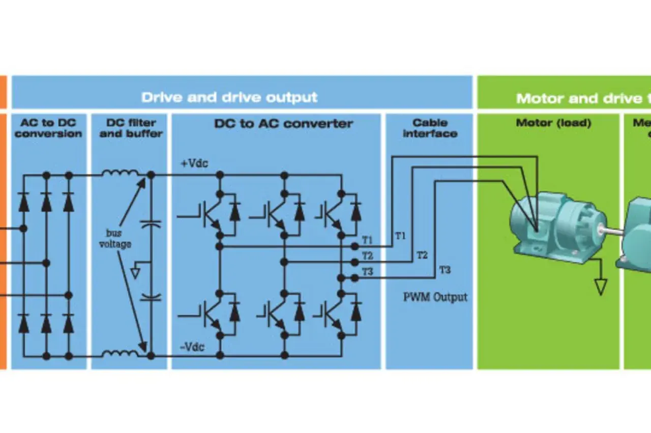
I treat the DC link as the part of the drive that makes everything else possible. The incoming AC is rectified to DC, the capacitor bank smooths that DC, and the inverter stage turns it back into a controlled AC waveform for the motor. Because the inverter can only work with the energy already sitting on the bus, the bus voltage sets the ceiling for available output voltage, especially when the machine is accelerating hard or running near base speed.
For a three-phase diode bridge, the nominal DC bus is roughly 1.35 times the line-to-line supply voltage. That is why a UK 400 V panel typically produces a bus in the neighborhood of 540 V DC, not 400 V DC. The exact reading changes with the input network, the drive’s front end, and whether the drive is designed for simple rectification or active regulation.
Once you see the bus as an energy buffer rather than a random number, the next question is whether the value you are seeing is actually normal for the supply class.
What normal values look like on UK industrial supplies
On UK sites, the most common reference point is a 400 V three-phase supply at 50 Hz. In that case, I expect a diode-front-end drive to show roughly 540 V DC at idle, with 415 V equipment sitting around 560 V DC. Higher-voltage classes are just scaled versions of the same idea.
| Input supply | Typical nominal bus | What it means in practice |
|---|---|---|
| 230 V single-phase | About 325 V DC | Common on smaller drives and light-duty machines |
| 400 V three-phase | About 540 V DC | The standard reference point for most UK industrial panels |
| 415 V three-phase | About 560 V DC | Still seen on older labels and legacy equipment |
| 480 V three-phase | About 650 V DC | Useful when comparing manuals across regions and machine lines |
| 690 V three-phase | About 930 V DC | Used on larger systems where insulation and protection become more critical |
Two details matter more than the exact number. First, a healthy bus is usually steady at the same operating point, not perfectly flat. Second, active-front-end and boosted topologies can hold the bus to a setpoint instead of letting it float with the supply, so manual values always beat folklore when you are commissioning a specific model.
When the bus stops behaving like a stable reference, the fault pattern usually tells you whether the problem is coming from the supply, braking, or the load itself.
When the bus goes the wrong way and what it usually means
| Pattern | Most common cause | What it does to the machine | First thing I check |
|---|---|---|---|
| Bus climbs during decel | Regenerated energy has nowhere to go | Trip on stop, especially on high-inertia or vertical loads | Braking resistor, regen path, decel ramp |
| Bus sags on accel | Weak supply, loose feed, phase loss, undersized transformer | Undervoltage fault, poor torque, sluggish start | Incoming line voltage under load |
| Bus ripple is excessive | Aging capacitors, rectifier damage, missing choke, imbalance | Heat, nuisance trips, unstable torque | Capacitor health and input balance |
In motion-control systems, overvoltage is often a braking story. A spindle with heavy rotational inertia, a conveyor that stops too sharply, or a hoist that overhauls the load can all push energy back into the drive faster than the bus can absorb it. Undervoltage is the opposite: the drive wants energy, but the supply cannot deliver it cleanly enough, so torque headroom disappears just when the machine needs it most.
I also pay attention to ripple. A bus that is noisy only under one specific load may be telling you about the process; a bus that is noisy all the time often points to the hardware in the drive or the incoming supply. That distinction saves a lot of pointless parameter changes, and it leads straight into how I measure the problem instead of guessing at it.

How to measure it safely and avoid misreading the display
Measure at the same operating state each time: idle, accelerating, braking, or at a defined load point. If you compare a no-load reading to a deceleration reading, you are comparing different energy states, not the same bus. Most false alarms come from that mistake.
- Lock out the drive and wait for the capacitors to discharge exactly as the manual requires.
- Use a meter rated for the cabinet environment and for the voltage class you are working in.
- Measure between DC+ and DC- or the terminals specified by the manufacturer.
- Check the drive display and the meter together, then note whether they disagree by a small stable amount or by a large moving gap.
- Log the bus, the incoming line voltage, and the motor state at the same moment.
Two cautions matter here. First, some drives show a filtered estimate rather than a raw instantaneous reading, so a small mismatch is not automatically a fault. Second, a live bus can hold enough stored energy to damage test equipment or injure a technician; if the panel procedure is not clear, stop and follow the site isolation rules rather than improvising.
Once the reading is trustworthy, the real work becomes choosing the right way to keep the bus inside its normal window during acceleration and braking.
How to stabilise bus voltage in motion applications
There is no single fix for a drifting bus. The right answer depends on whether you are dealing with a short braking pulse, a repetitive stop-start cycle, or a multi-axis machine that trades energy between axes. In practice, I separate the options by where the energy goes.
| Method | Best fit | Strength | Trade-off |
|---|---|---|---|
| Braking resistor | Intermittent decels on single drives | Simple, predictable, and relatively low cost | Heat, cabinet space, and resistor sizing matter |
| Regen unit or active front end | Frequent braking, vertical loads, energy recovery | Returns energy to the supply and controls the bus more tightly | Higher cost and more commissioning effort |
| Common DC bus | Coordinated multi-axis machines | Lets one axis reuse energy from another | Needs system-level design and fault coordination |
| Line reactor or DC choke | Ripple reduction and nuisance-trip reduction | Smoother bus and lower stress on components | Will not solve major regenerative energy by itself |
| Longer decel or jerk tuning | Loads with enough stopping distance | No extra hardware and often the fastest fix | May lengthen cycle time or be unusable on vertical axes |
A holding brake is not the same thing as a dynamic braking solution. It keeps a load from moving when the machine is stopped; it does not magically absorb the energy of a hard deceleration. For high-inertia spindles, hoists, cranes, and winders, the real decision is usually between burning energy in a resistor, returning it to the supply, or sharing it across a common bus.
If the machine has multiple axes, I prefer a common DC bus or coordinated regen when one axis frequently brakes while another accelerates. That lets one axis reuse energy from another instead of throwing it away as heat. The last step is turning those design choices into a simple commissioning habit.
What I would check first on a real machine
When a drive starts tripping, I begin with the simplest questions before I touch parameters. Most bus problems are not mysterious; they are just easier to ignore than to trace properly.
- Confirm the supply class and drive rating match, including single-phase versus three-phase input.
- Check the bus at idle and under load. If it only fails on stop, treat it as a braking issue first.
- Inspect the braking resistor, chopper wiring, or regen module for heat damage and loose terminations.
- Look for supply imbalance, phase loss, loose terminals, or transformer taps that do not suit the site.
- Review inertia, deceleration time, and load direction. Vertical loads and overhauling loads are not the same as pumps or fans.
- For multi-axis machines, confirm whether energy sharing through a common DC bus was intended and correctly configured.
In a UK 400 V panel, a steady bus around 540 V DC is usually ordinary; the real clue is how the number behaves during start, stop, and regeneration. If you keep the supply, braking path, and motion profile aligned, the bus becomes a diagnostic window instead of a nuisance fault, and that is where the fastest gains in motion control usually appear.