What matters most about gearbox function
- A gearbox reshapes motor output into the speed and torque the machine actually needs.
- It can also change shaft direction and help a motor stay in a more efficient operating band.
- In motion control, low backlash and high torsional stiffness matter as much as ratio.
- Planetary and helical gearboxes suit most automation axes; worm gearboxes trade efficiency for compactness and sometimes load-holding.
- The right choice depends on torque, speed, duty cycle, mounting space, and thermal limits, not ratio alone.
What a gearbox actually does in a power train
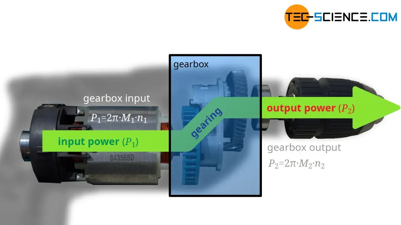
I think of a gearbox as a mechanical adaptor between the motor and the load. It does three things well: it reduces speed, multiplies torque, and, in some layouts, changes the axis of rotation. Just as important, it lets the motor stay closer to the speed range where it is efficient and controllable, instead of forcing the motor to do every job directly.
The important caveat is that a gearbox does not create power. In an ideal drive, power stays the same while speed and torque move in opposite directions; in a real drive, friction, lubrication losses, and gear mesh behaviour take a small slice out of the output. I never describe a gearbox as making a machine “stronger” in the abstract. It changes the way available power is delivered, which is the part that actually matters in the field. Next, it helps to look at the mechanics behind that trade-off.
How a gearbox changes speed, torque and direction
The simplest way to understand the ratio is to treat it as a swap. If the gearbox has a 10:1 reduction, the output shaft turns at roughly one-tenth of the input speed and delivers roughly ten times the torque before losses. That is why a small motor can move a much heavier load once the gearing is matched correctly.
- Speed reduction: lower output speed gives the machine better control at the point of use.
- Torque multiplication: the load gets more turning force without needing a larger motor.
- Direction change: bevel and worm designs can turn motion through 90 degrees.
- Mechanical trade-off: friction turns a portion of the input energy into heat, so efficiency always matters.
That trade-off becomes more pronounced as the ratio rises. In compact drives, a higher ratio can solve a space problem, but it can also increase heat, slow response, and reduce backdrivability. In other words, the gearbox is not just changing motion; it is shaping how the whole drive behaves. That is exactly why motion control engineers care so much about it.
Why motion control systems still depend on gearboxes
In motion control, the gearbox is not just a torque tool. It is part of the control strategy. A servo motor may be fast and precise on its own, but when the application needs more output torque, lower output speed, or a stiffer response, a gearbox can make the axis behave properly without forcing the motor to be oversized.Three motion-control effects matter most. Reflected inertia drops at the motor side, so the drive does not have to work as hard to accelerate the load. A 5:1 ratio reduces reflected load inertia by roughly 25:1 at the motor shaft, before gearbox inertia is added. Backlash, the tiny free play between gear teeth, has to be kept low so position reversals stay accurate. Torsional stiffness, which is how much the gearbox twists under load, affects how crisp the axis feels when the controller commands a move. In a pick-and-place head, indexing table, or robot joint, those details are the difference between repeatable motion and a system that constantly hunts or overshoots. The next question is which gear design fits those demands best.
Which gearbox type fits which job
When I compare gearboxes, I start with the application rather than the catalogue. The same ratio can be delivered by several designs, but the right choice depends on efficiency, backlash, noise, footprint, and how often the axis reverses.
| Type | Where it shines | Trade-off |
|---|---|---|
| Helical | Smooth, efficient power transmission for conveyors, general industrial drives, and moderate-speed machinery. | Not the best choice when you need a right-angle layout or ultra-compact packaging. |
| Planetary | Compact servo axes, robotics, indexing systems, and applications that need high torque density and low backlash. | Usually costs more than simpler gearsets and needs correct sizing to avoid added inertia problems. |
| Bevel or right-angle | Installations where the input and output shafts must meet at 90 degrees. | More sensitive to alignment and often less forgiving than a straight-through layout. |
| Worm | Very compact drives with high single-stage reduction and, in some cases, load-holding behaviour. | Efficiency can fall sharply at high ratios, which means more heat and more attention to lubrication. |
| Harmonic or strain wave | Ultra-precise positioning, especially in robotics and small, highly controlled axes. | Less tolerant of shock loads and usually more expensive than mainstream industrial options. |
For many general automation jobs, planetary and helical units are the sensible starting point. Worm gearboxes still earn their place when compactness or holding behaviour matters more than efficiency, and bevel designs are the practical answer when the layout forces a right-angle drive. I would not pick any of them by habit alone. The load profile decides, not the brochure. That leads directly to the part where most projects either succeed quietly or fail expensively.
How I would choose one for an automation axis
I usually ask six questions before I shortlist a gearbox: what is the peak torque, what is the continuous torque, what speed range does the axis need, how often does it accelerate and reverse, what backlash can the process tolerate, and how much space is available around the shaft. If the answer to any of those is vague, the specification is probably too vague as well.- Match torque to the real duty cycle. Continuous and peak torque are not the same thing. A gearbox that survives a peak once may still overheat in continuous use.
- Set the ratio from speed and resolution, not guesswork. Too little reduction leaves the motor struggling; too much can make the output slow and narrow the usable speed range.
- Check backlash and stiffness together. Low backlash without enough stiffness still produces poor positioning under load.
- Look at thermal limits. Efficiency losses become heat, and heat shortens lubricant life and reduces reliability.
- Confirm mounting and environment. Shaft orientation, contamination, washdown, dust, vibration, and ambient temperature all affect real-world life.
- Leave margin for shocks. Frequent starts, stops, and reversing loads justify a higher service factor.
The most practical rule is simple: size for the machine cycle, not the headline number. That mindset avoids most of the failures I see in the field. Once you do that, the common mistakes become easier to spot.
The mistakes that cause noisy, hot or inaccurate axes
The failures that frustrate teams usually come from optimism, not from the gearbox itself. The drive was specified for nominal torque, but the machine sees shock loads. The axis needed low backlash, but a general-purpose reducer was fitted. The layout needed right-angle output, but the installer tried to force a straight-through unit into a cramped frame.
- Choosing ratio first and application second. The result is often a motor that runs hot or an axis that moves too slowly.
- Ignoring backlash in reversing motion. Even a small amount of free play can ruin indexing accuracy.
- Overlooking motor tuning after the gearbox is added. The servo loop that behaved well without gearing may oscillate once the reflected inertia changes.
- Underestimating heat. Worm gearboxes, in particular, can become inefficient at high ratios and heavy duty.
- Skipping alignment and lubrication checks. Small installation errors turn into noise, wear, and early failure.
When a gearbox is noisy, hot, or inaccurate, I usually treat that as a specification problem before I treat it as a component problem. That distinction saves time, because the fix is often in sizing, mounting, or control tuning rather than a wholesale redesign. The last piece is knowing what to expect from efficiency, maintenance, and lifecycle cost.
What efficiency, noise and maintenance really mean in practice
Real gearboxes all pay some penalty for turning motion into a more useful form. Efficiency losses become heat, heat affects lubricant, and lubricant condition affects life. That is why a gearbox that looks cheap at purchase can become expensive in energy or maintenance if the duty cycle is heavy.
| Factor | What to expect | Why it matters |
|---|---|---|
| Efficiency | Helical and planetary units are often around 94-98% efficient per stage; worm gearboxes can vary from roughly 50% to the low 90s, with high ratios landing lower. | Lower efficiency means more heat and higher running cost. |
| Noise | Smoother tooth engagement usually means quieter operation. | Noise often tracks with friction, misalignment, and wear. |
| Maintenance | Lubrication, seal condition, and alignment checks matter more than most buyers expect. | Neglect shows up as backlash growth, temperature rise, and shortened service life. |
In practice, I prefer to think in terms of lifecycle value rather than purchase price. A gearbox that is slightly more efficient, easier to cool, and more stable under load usually pays for itself in uptime. That is the perspective that makes the final answer useful in an automation setting.
The practical rule I use when specifying motion systems
If I had to reduce the whole topic to one line, it would be this: choose the gearbox that gives the load the motion it needs while keeping the motor in its efficient and controllable zone. That means balancing ratio, backlash, stiffness, thermal behaviour, mounting constraints, and the real duty cycle instead of chasing one impressive number.For general industrial automation, planetary and helical gearboxes are often the safest starting point. Worm units still make sense when compactness or holding behaviour matters more than efficiency, and bevel designs are the practical answer when the layout needs a right-angle drive. The right choice is rarely the fanciest one; it is the one that stays accurate, cool, and predictable after months of real production use.
That is the practical purpose of a gearbox in mechanical power transmission: it turns raw motor motion into controlled machine motion that the process can actually use.