The practical takeaways for reliable rotating equipment
- Most unbalance problems show up as a strong 1x running-speed vibration, but not every 1x peak is a balance issue.
- Static, couple, and dynamic unbalance behave differently and need different correction strategies.
- A proper job starts with inspection, vibration measurement, phase data, and a check for looseness, misalignment, or bearing wear.
- Single-plane correction suits simpler rigid rotors; two-plane work is usually needed when the rotor wobbles or the ends move differently.
- Field correction is useful for large installed rotors, but it should not be used to hide a mechanical defect.
Why imbalance matters in motion control
In motion control, unbalance matters because centrifugal force rises fast with speed. A small offset in the centre of mass becomes a much larger load at operating rpm, so a fan, spindle, pump, or servo-driven rotor can look acceptable at idle and still shake hard in service.
That extra load shows up as bearing heat, reduced life, audible noise, and less stable feedback. In precision axes, the controller ends up fighting a disturbance that should never have been there, which can reduce repeatability and make tuning less forgiving.
The diagnostic clue is often a strong 1x component, meaning vibration at the running speed. I still avoid jumping to conclusions, because bent shafts, looseness, coupling issues, and resonance can also create a 1x-looking problem. The first step is to separate the symptom from the root cause, and that leads naturally to the shape of the unbalance itself.
The three imbalance patterns I check first
I separate unbalance into three behaviours because they do not correct in the same way. If the wrong one is assumed, the repair often becomes a repeat job.
| Pattern | How it behaves | What usually fixes it |
|---|---|---|
| Static unbalance | The rotor has one heavy spot and tends to settle in the same angular position when stationary. The vibration is usually dominated by the running-speed component. | A single correction plane can be enough if the geometry is simple and the rotor behaves rigidly. |
| Couple unbalance | Equal and opposite end effects can cancel at rest, so the rotor looks fine when stopped, but it wobbles in rotation. The ends move out of phase. | Two-plane correction is usually required because the problem exists across the shaft length, not at one point. |
| Dynamic unbalance | This is the combination most plants meet in the real world. It mixes static and couple effects, so the machine can vibrate in more than one mode. | Usually a two-plane job, and sometimes more complex correction if the rotor is long or begins to flex at speed. |
There is one more distinction I always keep in mind: rigid versus flexible behaviour. A rigid rotor can often be corrected at operating speed and stay within tolerance. A flexible rotor bends as speed rises, so a correction that looks good at low speed may not hold at service speed. In that case, influence-coefficient methods or modal balancing become relevant, because the rotor is no longer acting like a solid lump.
That distinction matters more as machines get faster and lighter, which is exactly why the next step is not to add weight blindly, but to follow a controlled process.
What a proper balancing job looks like
The best balance jobs are boring in the right way. They begin with mechanical inspection, because a dirty, damaged, or loose rotor can never be made trustworthy by adding correction mass. I check for bearing condition, soft-foot, looseness, coupling issues, blade damage, missing fasteners, and anything that changes the rotor geometry after it leaves the stand.
Then I measure the baseline. That usually means overall vibration, the 1x component, and a phase reference from a tachometer or keyphasor, which is simply a once-per-revolution timing pulse. If the speed changes during the test, I prefer order-based analysis rather than relying on a plain FFT, because it keeps the vibration tied to shaft speed instead of smearing the data.
- Confirm the mechanical condition before touching balance weights.
- Record the starting vibration and phase at the operating speed.
- Choose one correction plane or two, depending on geometry and behaviour.
- Add a trial weight or let the balancing calculator capture the influence response.
- Apply the computed correction in the right plane and at the right angle.
- Re-test at operating speed and verify that the residual vibration is acceptable.
- Document the as-found and as-left condition so the next maintenance visit starts from facts, not memory.
I am cautious about the trial-weight step. Too little weight gives a noisy response that is hard to interpret; too much can create an unsafe excursion. The useful goal is not just to make the vibration smaller, but to make the machine behave predictably enough that the correction can be trusted.
Shop balancing or in-situ correction
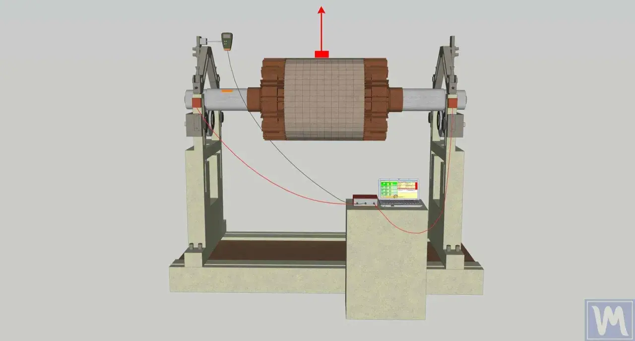
Choosing where to correct the unbalance is just as important as choosing how. If the rotor can be removed, a balancing machine gives you a controlled environment and repeatable measurements. If the rotor is large, tightly coupled to the process, or expensive to dismantle, on-site correction may be the better choice.
| Approach | Best for | Strengths | Limits |
|---|---|---|---|
| Workshop correction | Removed rotors, overhaul work, repeatable production parts | Controlled setup, easier documentation, clean testing conditions | It does not always capture installed-system effects such as base flexibility or coupling behaviour |
| In-situ correction | Large fans, blowers, pumps, turbines, and other installed rotors | No dismantling, real operating conditions, less downtime | Access and safety constraints, more sensitivity to plant conditions, and a higher risk of confusing balance with another fault |
| High-speed correction | Flexible rotors that change shape as speed rises | Matches correction to the speed where the rotor actually operates | More complex, often requires several speed points and tighter instrumentation discipline |
This is where the current ISO 21940 series is useful in practice: it separates rigid, flexible, and in-situ work instead of pretending that one rule fits every rotor. I like that approach because it matches how machines behave in the field. A long, lightly built impeller is not the same thing as a rigid coupling hub, and the correction method should reflect that.
When the machine is too valuable to remove, or when the installation itself influences the vibration pattern, on-site correction often gives the better result. That said, it only works well when the measurement chain is solid, which brings me to the part many teams underinvest in.
The measurements that stop guesswork
Balancing is a measurement problem before it is a correction problem. If the data is weak, the correction will be weak too. I start with vibration amplitude and phase, then add speed information so I can see whether the issue stays locked to running speed or shifts as the machine ramps.
- Acceleration or velocity readings from the bearing housing, which show whether the disturbance is growing with speed.
- Phase reference from a tachometer or keyphasor, which tells me where the heavy spot is relative to rotation.
- FFT or order analysis, with order analysis preferred when speed changes because it keeps the signal tied to shaft speed.
- Run-up and coast-down data, which helps reveal resonance and separates a balance issue from a structural one.
- Temperature and bearing condition, because a damaged bearing can mimic a balance fault or make a small imbalance look much worse.
The important point is that unbalance is often steady and repeatable, while other defects are less tidy. A machine that changes character dramatically near a critical speed may need a different fix altogether, and I would rather discover that before adding correction mass than after.
Once those measurements are in place, the remaining risk is not ignorance, but the kind of avoidable mistake that makes a straightforward job unnecessarily expensive.
Common mistakes that waste time and money
Most failed balance jobs are not caused by the calculation. They are caused by the setup, the mechanical condition, or a false assumption about what the vibration means.
- Balancing a dirty or mechanically damaged rotor and expecting the correction to hold.
- Ignoring soft-foot, looseness, or alignment faults and treating every 1x peak as an unbalance problem.
- Using a single-plane approach on a rotor that clearly needs two-plane correction.
- Forgetting that a keyway or fitted key changes the effective mass distribution if it is not handled consistently.
- Correcting the rotor on the bench and then reassembling it in a way that changes the final condition.
- Chasing a flexible rotor with rigid-rotor logic and assuming the first good reading will hold at speed.
I see one particularly expensive pattern in plants that run hard: the team keeps adding weight to a rotor that was never the real fault. The machine gets quieter for a day, then the vibration comes back because the underlying issue was bearing wear, looseness, or a mounting problem. That is why a balance job should always be part of a wider inspection, not a shortcut around one.
How I would build this into a modern maintenance programme
In a modern plant, I would not treat balancing as an isolated workshop activity. I would fold it into condition monitoring, work-order history, and post-maintenance verification so the next technician can see what changed and why. That matters in smart manufacturing because the useful data is not just the final vibration reading, but the path from fault to correction.
- Keep a baseline for each critical asset, including vibration, speed, temperature, and operating load.
- Store correction angle, correction mass, and final residual readings in the CMMS or asset platform.
- Repeat checks after blade cleaning, impeller replacement, bearing change, coupling work, or any rebuild that changes mass distribution.
- Use trend alarms to catch drift early instead of waiting for a visible increase in noise or heat.
- Train technicians to stop and inspect when the data points away from unbalance, instead of forcing a balance-only fix.
Used well, rotor balancing is not a one-off workshop task but part of a wider reliability routine. When I tie the correction data to vibration trends, speed, temperature, and work-order history, the plant learns faster, repeats fewer failures, and spends less time chasing avoidable vibration.