An overload relay protects a motor from sustained excess current and heat, not from every electrical fault. In a typical UK industrial starter, it works with the contactor and the short-circuit protective device so the motor can start normally, run safely, and stop before the windings are damaged. I’ll break down how it works, where it sits in the circuit, how the common types differ, and how to set one without guessing.
Key points at a glance
- An overload relay watches for persistent overcurrent and thermal stress, not brief starting spikes.
- It usually trips the contactor coil or control circuit, which stops the motor before damage builds up.
- It is not a short-circuit protective device; that job belongs to a fuse, breaker, or motor protection breaker upstream.
- IEC-style relays commonly use trip classes 5, 10, 20, and 30 to match different motor starting times.
- Thermal relays are simple and proven; electronic relays add precision and more fault information.
- The safest starting point is to match the relay to the motor nameplate current, then verify the trip class and reset mode.
What an overload relay actually does
I think of an overload relay as the motor’s thermal watchdog. It estimates how hot the motor is running by watching current over time, and if the load stays too high for too long, it opens the control circuit and removes the motor from service.
That matters because motors are often damaged by sustained overloads rather than dramatic faults. A jammed conveyor, a pump running against abnormal pressure, or a fan working harder than intended can all keep drawing excess current while the supply still looks “normal” to the rest of the system.
What it protects against
- Persistent overcurrent caused by an overloaded machine.
- Long starting periods that push the motor beyond its thermal limit.
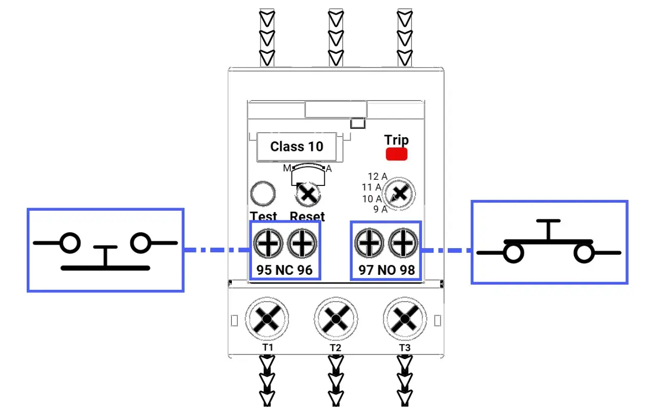
- Phase loss or phase imbalance on three-phase motors, depending on the relay design.
What it does not protect against
It does not clear short circuits. A dead short or high fault current is a different problem and needs a fuse, circuit breaker, or motor protection circuit breaker sized for that job. That distinction is easy to miss, and it is usually where protection schemes go wrong.Once that boundary is clear, the rest of the motor starter becomes much easier to read.
How it works inside a motor starter
In a standard starter, the contactor does the switching, the overload relay watches the motor load, and the short-circuit device protects the branch circuit. The overload relay is usually mounted directly to the contactor or wired very close to it so the whole assembly behaves as one coordinated unit.
| Component | Job | Why it matters |
|---|---|---|
| Contactor | Turns the motor on and off under control signal | Handles the switching duty, not the overload detection |
| Overload relay | Detects sustained excess current or thermal stress | Prevents winding damage and nuisance downtime from a hot motor |
| Fuse or circuit breaker | Clears short circuits and severe fault currents | Protects the supply wiring and the starter from catastrophic faults |
In UK industrial panels, that layout is common in pump sets, conveyors, compressors, HVAC plant, and general machine controls. I like it because each part has one clear job, which makes troubleshooting far easier than trying to force one device to do everything.
That separation of duties leads straight into the next question: which type of overload protection is the best fit for the application?
Thermal, electronic, and motor protection circuit breaker options
People often lump these devices together, but they are not identical. If I am specifying a starter, I always separate the question of how the motor is protected from heat from the question of how the circuit is cleared during a fault.
| Option | How it behaves | Strengths | Trade-offs |
|---|---|---|---|
| Thermal overload relay | Uses a thermal element, usually a bimetal mechanism, to react to sustained overload | Simple, robust, widely used, easy to understand | Less precise than electronic protection and more sensitive to ambient conditions |
| Electronic overload relay | Measures motor current directly and applies electronic logic to trip behaviour | More precise, often adds phase-loss, imbalance, stall, or jam detection | Costs more and may need a cleaner control environment |
| Motor protection circuit breaker | Combines overload and short-circuit protection in one device | Compact and convenient when the application suits it | Less flexible if you want separate protection functions or more detailed control features |
The practical point is this: if you want a straightforward starter for a standard motor, a thermal relay is often enough. If you need tighter protection, extra diagnostics, or more control over trip behaviour, I would look at an electronic relay. If you want one compact device to handle both overload and short-circuit duties, a motor protection circuit breaker may be the better architecture.
That choice only works if the relay is set up correctly, so the next step is matching the device to the motor rather than the other way around.
How to choose and set one correctly
The safest starting point is the motor nameplate. I usually set the relay to the motor’s rated current first, then check the manufacturer’s instructions for any adjustment limits, trip-class guidance, or service conditions that could change the setting.
Match the trip class to the starting profile
IEC-style relays commonly use trip classes 5, 10, 20, and 30. The class tells you how long the relay will tolerate a specified starting condition before it trips, so a motor with a short, clean start can use a lower class, while a machine with a longer acceleration period may need a higher one.
A class 10 relay is a common starting point for many standard motors. I would move to class 20 or 30 only when the motor manufacturer and the application both justify the longer start time.
Choose the reset mode with the process in mind
Manual reset is usually the safer default because it forces someone to look at the machine after a trip. Automatic reset can be useful in tightly controlled systems, but I would only use it when an unexpected restart cannot create a hazard.
Read Also: What are Line 1 and Line 2 in Electrical? UK Guide
Check the environment, not just the nameplate
Heat inside a crowded enclosure, poor ventilation, and neighbouring warm equipment can all affect a thermal device. Electronic relays are often more stable in those conditions, but they still need correct installation and wiring. In other words, a good setting is only good if the surrounding panel supports it.
Once those settings are right, the remaining errors are usually the simple ones that creep into rushed panel builds.
Common mistakes that cause nuisance trips or weak protection
- Setting the relay from cable size instead of the motor nameplate current.
- Using the overload relay as if it were short-circuit protection.
- Ignoring phase loss on three-phase motors.
- Choosing a trip class that is too low for a motor with a long acceleration time.
- Using automatic reset in a process that should be inspected after every trip.
- Mounting a thermal relay in a hot enclosure and then treating the nuisance trips as “bad hardware” rather than a design issue.
Most of these mistakes do not show up immediately. They appear later as repeated trips, overheated windings, or a motor that seems to “mysteriously” fail after a period of hard running. That is why I prefer to validate the protection scheme before the panel goes into service, not after the first complaint from production.
The check I would run before signing off a panel
If I were reviewing a starter in the UK market, I would run a short, practical checklist. Is the overload relay matched to the motor current? Does the upstream device clear short circuits? Does the trip class suit the acceleration time? Is phase-loss behaviour appropriate for a three-phase load? Is the reset mode safe for the process?
If the answer to those five questions is yes, the protection scheme is usually in good shape. The relay is then doing the job it was meant to do: catching the kind of overload that cooks a motor slowly, while the rest of the starter handles switching and fault clearing.
That is the real answer behind the question of what an overload relay is: a focused protection device for sustained motor stress, best used as part of a properly coordinated starter rather than as a standalone fix for every electrical fault.