In pump work, the number at zero flow is not a curiosity; it is the upper limit of head a pump can develop when the discharge is closed. That is the figure people often mean by head lift at 0 flow, and it matters because it tells you how a pump behaves at the left edge of its curve, how much static lift it can overcome, and where overpressure or overheating starts to become a real risk. This guide breaks down what the number means, how to read it on a curve, and how I use it when sizing fluid power systems in the UK.
What the zero-flow point tells you about a pump
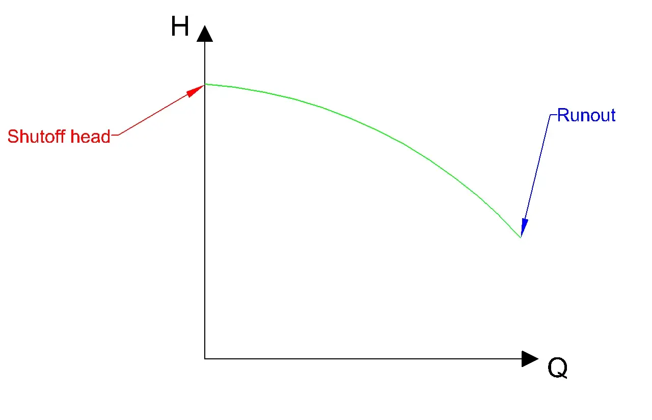
- Shut-off head is the maximum head at zero flow, not a point you should plan to run at.
- On a centrifugal pump curve, it is the left-hand intercept where flow drops to nothing and head is highest.
- In UK work, it is usually more useful to think in metres of head first and convert to bar only when comparing with system ratings.
- For positive displacement pumps, zero flow usually means a blocked outlet, so overpressure protection becomes essential.
- The duty point should sit near the best efficiency point, not near the zero-flow limit.
What the zero-flow point really means
For a centrifugal pump, the zero-flow point is usually called shut-off head or dead-head. It is the highest differential head the pump can produce at a given speed and impeller trim when no liquid is moving through the line. In plain terms, the pump is spinning, pressure is building, but flow has stopped.
I treat that number as a ceiling. It tells me the upper boundary of what the pump can do, but not what it should do continuously. Head is simply pressure expressed as an equivalent column of fluid, which is why it is so useful in fluid power work. Roughly, 10 m of water head is about 1 bar, so a pump rated at 25 m shut-off head is in the region of 2.5 bar at zero flow, before you factor in the specific liquid density.
This is also why the same pump can behave differently with different fluids. If the liquid is denser than water, the pressure at the same head is higher. If the liquid is hot or volatile, the margin before flashing or cavitation gets smaller. That is the part many catalog numbers hide, and it is why the next step is always to look at the curve itself.
How to read it on a pump curve
On a typical pump curve, flow sits on the horizontal axis and head on the vertical axis. The point where the curve meets the vertical axis is the shut-off head. As flow increases, head usually falls. That shape is normal for a centrifugal pump because more of the available energy is being used to move liquid rather than hold pressure against a closed or nearly closed discharge.
A compact way to read the curve is to ask three questions:
- What is the head at zero flow?
- What head do I need at the actual duty flow?
- Where is the best efficiency point, or BEP, relative to my duty point?
There is one practical UK detail worth stating plainly: check the curve at the speed you will actually use. A 50 Hz pump curve is not the same as a 60 Hz curve, and a variable-speed drive changes the picture again. I have seen more than one bad selection come from mixing those up.
Why operating there is usually a bad idea
Zero flow sounds harmless because nothing is moving, but inside the pump it is often the opposite. The liquid trapped in the casing is still being worked on by the impeller, and that energy turns into heat. If the pump stays there long enough, temperature rises, seal faces suffer, and the bearings and hydraulics start to feel it.
In practice, I would not treat shut-off as a normal operating point for a centrifugal pump. Many manufacturers and industry references warn that even brief operation at dead-head can cause damage if the system has no bypass, no minimum-flow path, and no thermal relief. The exact safe time varies with pump size, liquid, and cooling, but the broader rule is consistent: zero flow is a limit condition, not a steady-state target.
There are a few common failure paths here:
- Heat buildup in the trapped liquid
- Seal damage from local temperature rise
- Vibration and recirculation inside the casing
- Possible cavitation when the system is opened again without enough suction margin
- Motor loading issues if the installation pushes the pump outside its intended range
This is the point where system design matters as much as the pump itself. A good curve can still be a bad installation if the discharge can be closed accidentally and the liquid has nowhere safe to go.
Centrifugal and positive displacement pumps behave differently
The phrase zero flow means something different depending on the pump type. That distinction matters because people often use one rule from one technology and apply it to another, which is where expensive mistakes begin.
| Pump type | What zero flow means | Main risk | Design takeaway |
|---|---|---|---|
| Centrifugal | The pump reaches shut-off head at the left edge of the curve | Heat, seal damage, and unstable operation if it is held there | Use a bypass or minimum-flow path if zero-flow is possible |
| Positive displacement | The pump still displaces a fixed volume per revolution, so a blocked outlet quickly creates overpressure | Pressure can rise until a relief valve, bypass, or driver limit intervenes | Overpressure protection is not optional |
| Hydraulic or fluid power circuits | Pressure may continue to rise even when useful flow stops | Line burst, valve damage, or stalled actuation | Check ratings for the whole circuit, not just the pump |
For positive displacement pumps, I am especially careful. The machine does not “settle” into a harmless zero-flow point the way people sometimes imagine. If the outlet is blocked, pressure climbs fast, so a relief valve or protected bypass is usually part of the basic design. That is a very different world from centrifugal pump selection, even though both get talked about under the same fluid power umbrella.
How I size around it in real systems
When I size a pump, I do not start with the shut-off number and work backward. I start with the duty point: the flow the process needs and the total head at that flow. Total head is the sum of static lift, friction losses, and any required discharge pressure converted into head. Only then do I check whether the pump curve still has margin at the operating point and whether the zero-flow limit is acceptable for the installation.
A simple example makes this clearer. Suppose a system needs 8 m of static lift, about 4 m of friction loss at design flow, and roughly 1 bar of discharge pressure. That pressure requirement is about 10.2 m of head, which puts the total demand near 22 m. In that case, a pump with a 30 m shut-off head may look comfortable, but the real question is whether it can still deliver the required flow at around 22 m. If the curve drops too sharply, the pump is the wrong fit no matter how strong the zero-flow number looks on paper.
That is also where control strategy comes in. If you expect the discharge valve to close, or the process to run at very low flow for periods of time, I would look for one of three things:
- A minimum-flow bypass back to tank or suction
- A relief or thermal protection strategy sized for the actual liquid and pressure
- A variable-speed control scheme that keeps the pump away from the far left side of the curve
One more practical point: do not ignore pipework and accessory ratings. The pump may tolerate a certain shut-off pressure, but the gauges, seals, hoses, and fittings might not. In the UK, I usually want the whole installation checked in bar and metres of head so that pressure ratings and hydraulic duty are compared on the same terms.
The details that separate a safe selection from an expensive mistake
When I review a pump selection, I look for five things before I sign off on it: the duty point, the shut-off head, the BEP location, the allowable minimum flow, and the protection plan if flow disappears. If any one of those is vague, the selection is not finished.
- Duty point - the flow and head the system actually needs
- Shut-off head - the maximum head at zero flow
- BEP - the most efficient operating zone
- Minimum flow - the lowest safe continuous flow, if the manufacturer gives one
- Protection - bypass, relief, thermal relief, or speed control
The habit that saves the most trouble is simple: read the full curve, not just the biggest number on the brochure. A high zero-flow head can be useful, but it does not prove the pump is a good fit for the process. The right pump is the one that meets the duty point safely, stays within its operating envelope, and leaves enough margin for the realities of the installation.