In a pneumatic circuit, the valve is the decision-maker: it sends compressed air to the right port, vents the wrong side, and makes a cylinder extend, retract, or hold position. The real challenge is not understanding the principle, but choosing the right function, porting, actuation method, and air quality for the job. This guide breaks down the valve logic, the common 3/2, 5/2 and 5/3 arrangements, and the checks that save time during commissioning and maintenance.
What matters most when choosing a pneumatic directional valve
- The job is simple: route compressed air to the correct port and exhaust the other side cleanly.
- 3/2, 5/2 and 5/3 functions cover most actuator needs, but the cylinder’s behaviour decides the best fit.
- Port identification matters: supply, working ports and exhausts should be read consistently, ideally against ISO marking conventions.
- Flow capacity, pressure rating and actuation style matter more in practice than the valve body alone.
- Dirty air, poor exhaust design and coil mismatch are common reasons a valve appears to fail.
How the valve routes air through a circuit
A directional valve does one thing very well: it connects and disconnects internal passages so the air reaches one side of an actuator while the other side is exhausted. In a spool valve, a sliding element uncovers one flow path and blocks another; in a poppet valve, a seat opens or closes more directly. The result is the same from the machine’s point of view, but the internal design affects flow, leakage, speed and how tolerant the valve is of dirt.
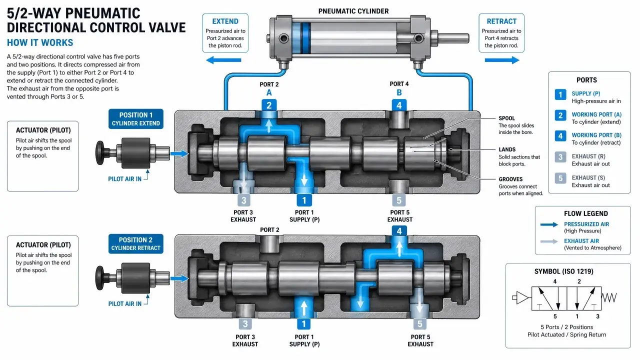
I usually start with the port map. In most pneumatic systems, port 1 is supply, ports 2 and 4 are working ports, and ports 3 and 5 are exhausts. ISO 11727 is the standard that helps keep that port identification consistent, while ISO 5599-1 is commonly used for five-port mounting interfaces. That matters because a machine builder in Birmingham and a component vendor in Munich can talk about the same circuit without guessing.
Actuation is the second layer. A valve may be shifted by a solenoid, by pilot air, by a lever, or by a pushbutton. Spring return means the valve goes back when the signal disappears; detent means it stays where it was left. Once you understand that switching logic, the next question is not “which valve is best?” but “which function matches the actuator I need to control?”
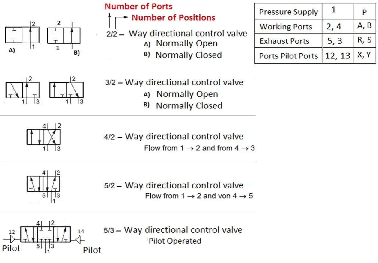
Choosing between 3/2, 5/2 and 5/3 functions
This is where most buying mistakes happen. The valve function has to match the actuator, not just the catalogue page. If you get this wrong, the machine may still move, but it will do so inefficiently, unpredictably, or with the wrong fail-safe behaviour.
| Valve function | Best fit | What it does at rest | Why I choose it |
|---|---|---|---|
| 3/2 | Single-acting cylinders, blow-off, vacuum release | One port is supplied, one is exhausted, one is blocked depending on the state | Simple, compact and usually the cleanest answer for one-way motion |
| 5/2 | Double-acting cylinders | Switches supply between two working ports | The default choice for extend/retract motion |
| 5/3 centre closed | Holding position without venting both sides | Both working ports are blocked in the middle | Useful when the actuator should stay where it is, though it is not a mechanical lock |
| 5/3 centre exhaust | Unloading, safe stop, free movement | Both sides vent in the middle | Good when you want the cylinder to relax or coast instead of being held under pressure |
| 5/3 centre pressure | Balanced or tensioned applications | Both working ports are pressurised in the middle | Useful in specific control cases, but only when the process really needs it |
A 5/2 valve is the workhorse for most double-acting cylinders because it gives a clean extend/retract sequence with little complication. A 5/3 valve adds a middle state, which can be valuable, but only if you actually need that intermediate behaviour. I would not pay for a 5/3 centre function just because it sounds more advanced; I would buy it because the machine needs a defined neutral state.
There is also a practical point that gets overlooked: a valve that is technically correct can still be wrong if the actuator needs a different fail position. For example, if a cylinder must retract on loss of signal, the rest position of the valve matters as much as the switching action. Once that is clear, the next decision is how the valve should be actuated and mounted on the machine.
Picking the actuation and mounting style that suits the machine
When I compare valves, I separate the switching function from the actuation method. That keeps the decision clean. A solenoid-operated valve is the usual choice in automated equipment because the PLC can drive it directly. A pilot-operated valve is often used when you want the electrical load to stay small while the valve handles more air. Manual and mechanical operators still matter in commissioning, maintenance and mobile equipment, where a technician may need to shift the valve without waiting for control power.
There is a tradeoff with pilot operation that deserves respect: the valve usually needs a stable air supply and the pilot side must be protected from pressure dips and backpressure. In other words, the bigger the valve system gets, the more important the surrounding air preparation and exhaust layout become. I also like having a manual override somewhere in the loop because it tells me quickly whether the problem is electrical, pneumatic or mechanical.
Mounting style is just as practical. Inline valves are easy to understand, but manifold mounting becomes more attractive as soon as a machine has multiple actuators. Parker’s manifold examples show why: shared supply and exhaust lines reduce tubing and make servicing easier, and a manifold can carry several valves together instead of scattering them across the frame. That matters in real automation, where the cost of maintenance time often beats the cost of the valve itself.
For the engineer trying to keep a build neat, manifolds also help with diagnostics. If several valves share the same air supply and one branch starts misbehaving, the fault boundaries are clearer than they are on a dense mess of individual fittings. That leads straight into the next question, which is how flow, pressure and port size shape actual performance.
What flow, pressure and port size really change in practice
Flow is where theory meets motion. A valve can have the right switching logic and still underperform if it cannot move enough air fast enough. The result is familiar: slow cylinder travel, weak force at the end of stroke, or a machine that behaves differently under load than it does on the bench. I treat the flow path, the hose length and the exhaust path as one system, not separate details.
Port size is not a vanity spec. Smaller ports usually mean a more compact valve, but also more restriction. Larger ports can improve throughput, but they add size, cost and sometimes a heavier exhaust noise problem. In one rugged product family from Parker, for example, G1/8 and G1/4 versions are designed for pressures up to 16 bar, while G3/8 and G1/2 versions are specified up to 12 bar. That is a reminder that size and pressure rating do not scale in a simple straight line; the exact body design matters.
In the same family, manifold bars are available with space for between 2 and 14 valves. That kind of detail tells me how the product is meant to be used: not just as a standalone component, but as part of a compact valve island. For machine builders, the benefit is less tubing and faster assembly. The cost is that the whole island becomes a single design decision, so the supply pressure, exhaust capacity and service access all need to be planned together.
When people say a valve is “too small”, they often mean one of three things: pressure drop across the valve is too high, response time is too slow, or the exhaust side is choking the circuit. I look for those separately, because the fix is not always to buy a larger valve. Sometimes the real answer is shorter tubing, a cleaner exhaust, or a more suitable manifold layout. That is why the next section matters so much: air quality and exhaust design are usually where the hidden losses start.
Why clean air and exhaust design prevent most faults
Most directional valve problems are not dramatic component failures. They are slow, annoying degradations that start with contamination, moisture or pressure loss. Dirt can make a spool stick. Water can corrode internals. Oil carryover can change seal behaviour. A blocked silencer can create backpressure that prevents the valve from exhausting cleanly. None of that looks like a big failure on paper, but it is enough to ruin cycle time.
I pay attention to air preparation before I blame the valve. The cleaner the air, the more predictable the valve life. Parker explicitly notes that service life depends on air cleanliness and points users toward ISO 8573, which is the right mindset: treat the air supply as part of the component’s operating environment, not an afterthought. If the application is dirty, wet or heavily cycling, filtration and drainage are not optional extras.
Exhaust design is another hidden issue. A valve may switch perfectly and still feel slow if the exhaust path is too restrictive. Silencers are useful, but they should not become a bottleneck. The same goes for tight fittings, long small-bore tubes and badly placed bends. These are small losses individually, but in a fast actuator circuit they stack up quickly.
When a valve misbehaves, I work through the symptoms in a fixed order: verify supply pressure, confirm coil voltage, check the manual override, inspect the exhaust, then look for contamination or worn seals. That sequence saves time because it separates electrical faults from pneumatic faults before anyone starts replacing parts at random. With that in mind, the last thing worth doing is turning all of this into a simple ordering checklist.
What I would verify before I place an order
Before I buy a valve, I want answers to the questions that create expensive returns when they are ignored. The part number only helps if the application has been pinned down properly.
- Actuator type: single-acting, double-acting, or a process function such as blow-off or vacuum release.
- Required rest state: spring return, detent, centre closed, centre exhaust or centre pressure.
- Supply conditions: pressure range, minimum pilot pressure if applicable, and whether the air is dry and filtered.
- Electrical interface: coil voltage, connector type, and whether the control system can drive the load directly.
- Flow and porting: valve size, hose size, exhaust capacity and whether a manifold will simplify the build.
- Environment: temperature, vibration, corrosion risk and how easy it will be to service the valve in place.
If I have those six answers, selecting the valve stops being a guessing game. That is the real value of understanding pneumatic directional control: not memorising symbols, but matching switching logic, air quality and machine behaviour so the system works the way the designer intended. In practice, that is what separates a neat circuit from one that keeps draining maintenance time.