A liquid flow control system is not just a valve in a pipe. In practice, it is the combination of valve, sensor, actuator, and logic that keeps liquid moving at the right rate, under the right pressure, and with enough stability for the process to behave consistently. In fluid power, that difference matters because flow affects speed, pressure affects force, and poor control shows up quickly as waste, noise, drift, or inconsistent output.
This guide explains how the circuit works, which components really decide performance, how to choose between simple throttling and closed-loop control, and what usually goes wrong when the liquid, the valve, or the instrumentation is not properly matched.
What matters most when you specify liquid flow control
- Flow sets speed; pressure sets force, so the two must be treated as separate design variables.
- Valve sizing alone is not enough; sensor quality, fluid cleanliness, and installation details shape real-world stability.
- Closed-loop control is worth the added complexity when the liquid varies, the batch must repeat, or manual trimming costs time.
- Magnetic, Coriolis, proportional, and pressure-compensated solutions each solve a different problem.
- The best circuits are the ones operators can commission quickly and diagnose without guesswork.
What the circuit actually controls in fluid power
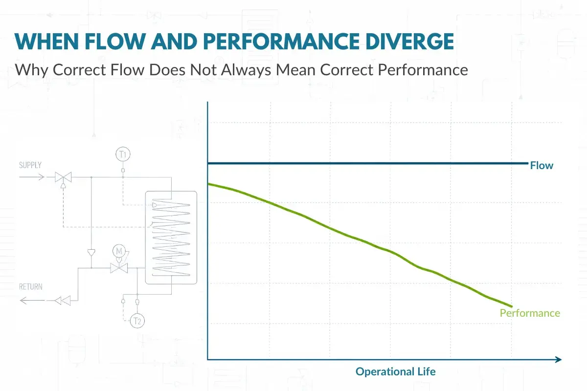
The first mistake I see is treating flow and pressure as if they are the same thing. They are related, but they do different jobs. Flow rate largely sets how fast an actuator moves, how quickly a tank fills, or how much liquid reaches a process point in a given time. Pressure is what creates force, holds a clamp, pushes through resistance, or overcomes a load.
That is why a circuit can look “fine” on paper and still behave badly in the plant. A throttling valve may deliver the right flow at one moment, then drift when upstream pressure or viscosity changes. In fluid power, that drift becomes speed variation, uneven motion, or a cycle time that operators keep adjusting by hand.
| Variable | What it mainly influences | What goes wrong when it drifts |
|---|---|---|
| Flow rate | Speed, fill rate, cooling rate | Slow cycles, overshoot, uneven filling |
| Pressure | Force, clamping, sealing performance | Weak actuation, leakage, higher pump load |
| Temperature | Viscosity and repeatability | Sluggish response, calibration drift, unstable control |
| Contamination | Valve life and response stability | Sticking, wear, false readings, maintenance downtime |
That split between flow and pressure is the foundation for every other design choice. Once that is clear, the next question is which parts of the circuit keep behaviour stable when the load changes.
The components that decide how stable the loop feels
In a good circuit, the valve is only one part of the story. The supply source, filter, sensor, controller, and piping layout all affect whether the system feels calm or twitchy. I usually look at the whole loop before I blame the valve.
| Component | Why it matters | What usually happens if it is neglected |
|---|---|---|
| Pump or supply source | Provides the energy and available pressure | Starvation, unstable delivery, poor headroom for control |
| Control valve | Meters or redirects the liquid | Hunting, overshoot, poor throttling, wasted pressure drop |
| Flow sensor | Tells the controller what the liquid is really doing | Wrong feedback, poor repeatability, false confidence |
| Pressure sensor | Shows load changes and loss across the circuit | Hidden restrictions, unnoticed overload, weak diagnostics |
| Controller or PLC | Compares setpoint to feedback and trims the output | Slow correction, oscillation, no useful alarms |
| Filter or strainer | Protects small clearances and sensor elements | Stiction, wear, clogging, shortened service life |
| Piping and fittings | Shape the pressure loss and flow profile | Noise, cavitation, erratic readings, hard commissioning |
If I had to improve one older line first, I would usually fix feedback and cleanliness before I reach for a more exotic valve. A solid loop with modest hardware often beats a clever valve installed in a messy circuit. That naturally leads to the bigger design question: do you need simple throttling, or do you need closed-loop control?
Which control approach fits the job
Not every application needs the same level of control. Some duties only need a stable, manual adjustment. Others need the loop to correct itself as temperature, viscosity, or load changes throughout the shift. The wrong approach is expensive in a different way every time: too simple, and operators do the tuning; too complex, and maintenance inherits a system nobody trusts.
| Approach | Best use | Strength | Limitation |
|---|---|---|---|
| Throttle or needle valve | Basic flow trimming, steady loads, low-cost circuits | Simple, compact, easy to understand | Flow shifts when pressure or viscosity changes |
| Pressure-compensated flow control | Hydraulic speed control with moderate load variation | More stable than plain throttling | Still not true feedback control |
| Proportional valve | Variable output with PLC input | Smooth modulation and better repeatability | Needs clean fluid and sensible tuning |
| Servo valve | Very precise motion or fast response | Excellent control quality | Higher cost and tighter cleanliness demands |
| Closed-loop valve plus meter | Dosing, batching, recipe changes, variable fluids | Best repeatability when conditions move around | More components and more commissioning effort |
My rule of thumb is straightforward: if the process can tolerate a little drift, keep the circuit simple. If the process cannot tolerate drift, buy the feedback. That is especially true when the liquid changes with temperature, when the load varies across the cycle, or when operators keep touching the setpoint to compensate for a design that was never really stable. Once that choice is clear, sizing becomes much easier.
How I would size and specify one
When I size a loop, I start with three numbers: minimum flow, normal flow, and peak flow. Then I check the liquid itself, because water, oil, coolant, syrup, and chemicals do not all behave the same way. Viscosity, conductivity, temperature range, solids content, and aeration all matter more than the catalogue photo suggests.
A useful sizing habit is to keep the control element working in the middle of its travel band during normal operation, rather than living almost shut or nearly wide open. As a practical target, I prefer roughly 20% to 80% valve travel for the duty point. Outside that range, the loop often becomes touchy or loses resolution. I also use Kv/Cv as a fast sanity check, because it links the valve, the pressure drop, and the actual liquid in a way that is hard to argue with.| Specification item | What I check | Why it matters |
|---|---|---|
| Flow range | Minimum, normal, and peak demand | Prevents oversizing and weak low-end control |
| Pressure conditions | Upstream pressure, downstream pressure, and available drop | Shows whether the valve can actually modulate the liquid |
| Liquid properties | Viscosity, conductivity, solids, temperature | Controls sensor choice, valve behaviour, and maintenance load |
| Control element size | Kv/Cv and working travel band | Separates a stable design from one that is always near the edge |
| Feedback device | Accuracy, signal type, installation requirements | Bad feedback makes good hardware look unreliable |
| Integration | PLC, IO-Link, analogue signal, or fieldbus | Determines how easily the circuit can be monitored and tuned |
| Maintenance access | Filter change, cleaning, calibration, valve service | Reduces downtime and avoids rushed fixes |
For sensing, I usually keep the choice practical. Magnetic flowmeters make sense for conductive liquids and low-maintenance operation; Coriolis is stronger when mass flow, density, and high accuracy matter; simpler differential-pressure or turbine-style options can still work when the fluid is well behaved and the budget is tighter. The point is not to use the most advanced sensor. It is to use the one that gives trustworthy feedback with the least operational friction. That same logic shows up very clearly in plant applications.
Where these systems earn their keep in plants
The best applications are the ones where stable liquid movement affects quality, throughput, or safety in a visible way. In those cases, flow control is not a side feature. It is part of the process itself.
| Application | Why control matters | What usually works best |
|---|---|---|
| Hydraulic presses and clamping | Speed consistency affects cycle time and part quality | Pressure-compensated or closed-loop control |
| Dosing and batching | Repeatability directly affects product consistency | Metered closed-loop control with reliable feedback |
| Cooling and lubrication circuits | Under-flow raises temperature and wear | Stable throttling plus good monitoring |
| Washdown and cleaning lines | Coverage and flow stability affect hygiene and turnaround time | Simple control with robust materials |
| Water treatment and utility skids | Transfer reliability affects uptime and compliance | Measured control with clear alarm handling |
In UK manufacturing, I still see plenty of older hydraulic plant running alongside newer automation. The useful upgrade is rarely “more valves”. It is usually better repeatability, better alarms, and less manual trimming by the operator. That becomes obvious once you start looking at failure modes instead of brochures.
The faults that cost the most time
Most complaints about unstable flow are really symptoms of one of a handful of issues. The good news is that the same small set of checks solves a large share of them. The bad news is that people often chase the wrong part first.
| Symptom | Likely cause | First thing I would check |
|---|---|---|
| Flow hunts or oscillates | Oversized valve, aggressive tuning, or delayed feedback | Valve sizing, controller gain, and sensor response |
| Output is slow or weak | Restriction, low supply pressure, blocked filter | Pressure drop across the circuit and filter condition |
| Readings jump around | Air in the line, poor meter placement, unstable fill level | Ventilation, installation orientation, and full-pipe conditions |
| Valve sticks or responds late | Contamination, wear, or viscous fluid at the wrong temperature | Cleanliness, seal condition, and liquid temperature |
| Excess heat | Too much throttling loss or unnecessary pressure drop | Where energy is being wasted in the circuit |
| Noise or water hammer | Sudden closure, poor ramping, or pressure spikes | Opening and closing profiles, plus any missing damping |
I would put contamination near the top of the list. A lot of “bad valve” stories are actually dirty fluid stories. Once the system is clean and the loop is measuring the right thing, tuning becomes much more predictable. That is also why 2026 systems are leaning harder into data.
Why 2026 systems are moving toward better data, not just better hardware
The most useful change I see in current industrial projects is not a dramatic new valve type. It is better visibility. Sensors now report more than a single process value, and that extra context helps controllers and maintenance teams make better decisions. Flow, temperature, conductivity, empty-pipe detection, actuator position, and diagnostic alarms all matter when a line has to run with less hands-on supervision.
IO-Link is a good example of the shift. It gives richer signal access without making the wiring messy, which is useful when a plant wants faster commissioning or cleaner integration with the controller and IT layer. A PLC, or programmable logic controller, can then use that information for alarms, recipe switching, trend logging, and more sensible fault detection. The value is not hype. It is faster diagnosis and fewer blind adjustments.
Still, I would not add digital layers to a circuit that is already poorly sized. Data cannot rescue bad hydraulics. If the valve is wrong, the filter is overloaded, or the sensor is in a bad location, the software will only tell you more clearly that the design is wrong. The smart move is to combine good physical design with just enough digital visibility to keep the process honest.
The details that separate a reliable circuit from a frustrating one
When I look back at systems that work well, they usually share the same traits: the valve is sized for the real liquid, the sensor is installed where the reading is trustworthy, the fluid stays clean enough for the hardware, and the control strategy matches the actual level of variability in the process. None of those are glamorous. All of them matter.
If I had to prioritise only three things in a new design, I would start with correct sizing, clean measurement, and contamination control. Get those right and the rest of the control strategy becomes easier to tune, easier to monitor, and much easier to maintain over time.