In fluid power, the number on the page only helps if it matches the way the circuit is actually built. When engineers talk about flow velocity units, they are usually asking for the standard way to express fluid speed, how to calculate it, and how it affects line sizing, noise, and pressure loss. I usually separate the topic into three parts: the unit itself, the calculation behind it, and the design limits that make the number meaningful.
The practical answer is simple: use metres per second for velocity and litres per minute for flow
- m/s is the standard SI unit for fluid velocity; ft/s is the common imperial alternative.
- Velocity is calculated from flow rate divided by area, so bore size changes the result immediately.
- In hydraulic circuits, suction lines should run slower than return lines, and pressure lines usually sit in the middle to upper range.
- L/min and gpm are flow-rate units, not velocity units, so they cannot be used interchangeably.
- On UK projects, I keep SI first and only add imperial figures when legacy equipment or a supplier document forces the issue.
What fluid velocity means in a power circuit
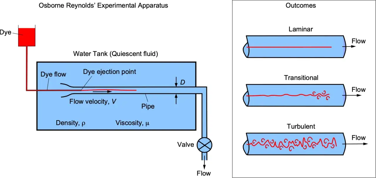
Fluid velocity is the average speed of the moving fluid through a defined section of pipe, hose, or channel. It is not the same as pressure, and it is not the same as volumetric flow rate. In practice, I treat it as the bridge between what the pump delivers and what the line can carry without wasting energy.
Average velocity is the number designers use
Real flow is not perfectly uniform across the pipe; the centre moves faster than the edges, and bends or fittings disturb the profile. For sizing work, though, we normally use average velocity, because that is the number that links directly to line area and pressure loss.
Why the distinction matters
A line can have a healthy flow rate and still be badly undersized if its bore is too small. That is when velocity jumps, friction rises, and the circuit starts paying for the mistake in heat, noise, or cavitation risk. Once that difference is clear, the next step is choosing the right unit system to read the data correctly.
The standard units engineers use and when each shows up
In SI-based work, the coherent unit for velocity is metres per second, written as m/s. That is the default I expect on modern UK drawings, calculations, and commissioning sheets. Imperial units still appear in imported equipment literature and older hydraulic references, where ft/s is the most common alternative. You may also see ft/min in older tables or calculators, but it is less convenient for fluid power line sizing.
| Quantity | Common SI unit | Common imperial unit | Why it matters in fluid power |
|---|---|---|---|
| Fluid velocity | m/s | ft/s | Used for pipe, hose, and duct sizing |
| Volumetric flow rate | m³/s, L/min | ft³/s, gpm | Used for pumps, valves, and system demand |
| Cross-sectional area | m², mm² | ft², in² | Used to convert flow into velocity |
I keep one unit system through the calculation and only convert once at the end if I need to share the result with a supplier or an older machine file. That habit avoids a surprising number of errors, especially when project data is also pushed into PLC tags or IoT dashboards.
How I calculate velocity from flow and bore size
The calculation is straightforward: velocity = flow rate divided by cross-sectional area. For a round pipe, the area is πd²/4, which means small diameter changes have a big effect on velocity. That is why the internal diameter matters more than the nominal size on the box.
Written another way, v = Q / A, where v is velocity, Q is flow rate, and A is area. If the passage is circular, you can substitute A = πd² / 4. The formula looks simple because the geometry is simple, but the practical impact is large.
A worked metric example
If a hydraulic line carries 60 L/min, that is 0.001 m³/s. Through a 20 mm internal diameter hose, the area is about 0.000314 m², so the average velocity is about 3.18 m/s. The same flow through a 32 mm hose drops to about 1.24 m/s. That is the whole story in one example: the flow did not change, but the velocity fell by more than half because the bore was larger.
Where the calculation can mislead you
Use actual internal diameter, not nominal size. Include the real section you care about, especially if filters, fittings, manifolds, or reducers create a smaller passage than the hose itself. If the run is long, or the fluid is more viscous than expected, the practical result can be worse than the neat calculation suggests.
Typical velocity ranges for hydraulic oil and why they matter
For hydraulic oil, velocity limits are usually design guidelines rather than hard rules. A useful starting point is lower velocity in suction lines, moderate velocity in return lines, and somewhat higher velocity in pressure lines. One UK hydraulic calculator I checked uses these guide ranges for oil around moderate viscosity: suction 0.625-1.25 m/s, return 1.5-3 m/s, and pressure 2.1-4.75 m/s.
| Line type | Typical velocity range | Why I keep it there | What I watch for |
|---|---|---|---|
| Suction line | 0.625-1.25 m/s | Reduces pressure drop and cavitation risk | Keep the intake line short and generously sized |
| Return line | 1.5-3 m/s | Balances heat, backpressure, and hose size | Watch the effect of filters, coolers, and bends |
| Pressure line | 2.1-4.75 m/s | Accepts more velocity, but friction still matters | Check pressure loss and noise before accepting the size |
These numbers assume ordinary hydraulic oil conditions, so I would not treat them as universal. Longer pipe runs deserve extra caution, and runs above roughly 10 m often justify a larger size rather than a borderline velocity. I am especially cautious on suction, because cavitation is expensive, noisy, and usually avoidable.
Read Also: Hydraulic Cylinder Mounts: Avoid Costly Failures
Hydraulics and pneumatics are not interchangeable
For compressed air, the same unit labels apply, but the sizing logic changes because gas is compressible. I would not take a hydraulic oil velocity range and apply it to an air header without rechecking pressure drop, density change, and duty cycle. The unit may be the same, but the behaviour is not.
Common mistakes that distort the number
- Using flow rate as if it were velocity. L/min and gpm tell you volume per time, not fluid speed.
- Using nominal bore instead of actual ID. The inside diameter is what controls area and therefore velocity.
- Skipping the area step. A unit conversion alone does not turn flow into speed.
- Mixing up line velocity with actuator speed. A cylinder rod moving at 50 mm/s is not the same thing as oil moving in the line at several m/s.
- Ignoring fittings and restrictions. A valve block, filter, or reducer can create a smaller effective passage than the hose suggests.
- Reusing hydraulic limits for other fluids. Water, oil, and air do not behave the same way under the same geometry.
I see the same pattern often in commissioning: the flow meter looks fine, the number on the screen looks calm, and yet the line runs hot because the real restriction was hidden in the hardware. Once those errors are out of the way, UK projects become much easier to keep consistent from drawing to commissioning.
How I choose units on UK projects without creating drawing chaos
My default is simple: use SI throughout the design chain. That means velocity in m/s, flow rate in L/min or m³/s, pressure in bar, length in mm or m, and temperature in °C. If a supplier gives me imperial values, I convert them once and keep the converted figure as the working reference rather than letting two systems drift side by side.
- Put the primary unit on the drawing and in the calculation sheet.
- Add the converted value in brackets only when a legacy part or supplier document needs it.
- State the actual fluid, temperature, and hose or pipe ID, not just the nominal size.
- Keep the same unit convention in PLC tags, maintenance notes, and digital dashboards.
- Recheck imported components against the real internal diameter before release.
This matters even more now that plant data is often exported into dashboards and condition-monitoring tools. Mixed units are a fast route to bad alerts, confused maintenance logs, and trend lines that look precise but mean very little. Once those errors are out of the way, the next step is a simple sign-off routine.
The three checks I use before signing off a line size
First, I confirm the unit basis is consistent. Second, I check the actual internal diameter, not the nominal label. Third, I ask whether the calculated velocity makes sense for the line type, length, and fluid. If any one of those three is shaky, I would rather revise the bore than defend a neat-looking number that will fail in service.
- Is the calculation using the same unit system end to end?
- Does the line type justify the velocity you are proposing?
- Will fittings, length, and fluid conditions change the real-world result?
For most fluid power work, the cleanest answer is still the simplest one: use m/s for velocity, keep L/min for flow, and never let nominal size stand in for actual bore. Get those three aligned, and the rest of the sizing conversation becomes much easier to trust.