The valve that controls actuator speed is often doing more work than it looks like. The flow control valve working principle is straightforward at heart: it creates a controlled restriction so a predictable amount of hydraulic fluid reaches the actuator, which in turn sets speed, timing, and movement quality. In this article I break down how that restriction works, why pressure compensation matters, and when meter-in or meter-out control gives the cleaner result.
What matters most before you adjust a flow control valve
- Flow, not pressure, mainly sets actuator speed in hydraulic circuits.
- A simple valve meters fluid with a variable restriction; a better one adds pressure compensation to keep the set flow steadier.
- Meter-out control is usually safer for overrunning loads, while meter-in suits simpler, resisting loads.
- Heat, cavitation, and contamination are the three problems I watch for first.
- In modern automation, the same mechanical principle still underpins proportional and electronically controlled valves.
What the valve actually does in a hydraulic circuit
The pump creates flow, the valve decides how much of it is allowed through, and the actuator turns that flow into motion. For a cylinder, speed is basically flow divided by piston area; for a motor, speed depends on flow and motor displacement. That is why two machines with the same pressure can behave very differently if the flow setting changes.
In UK plant rooms and mobile systems, I usually think in bar and litres per minute because those units make the speed-and-force relationship easier to read. Pressure gives you force reserve, but flow sets how fast the work gets done. Once you keep that distinction clear, the rest of the valve logic becomes much easier to follow, because you stop blaming the wrong component for a speed problem.
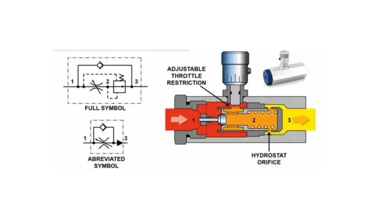
How the valve creates and maintains the restriction
At the simplest level, the valve uses a needle, poppet, or spool edge to change the opening size. Open the passage and more fluid passes; close it and the effective orifice gets smaller, so flow drops and the actuator slows. The relationship is not perfectly linear, which is why a small turn of the adjustment knob can sometimes matter a lot more than the last quarter-turn.
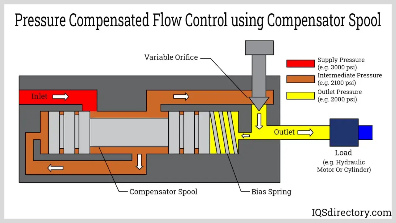
A pressure-compensated design adds a second element that senses the pressure drop across the restriction and keeps that drop near a target value. Parker’s industrial flow-control literature describes this type of valve as holding the selected flow within about 5% despite inlet and outlet pressure fluctuations, which is the difference between a valve that merely throttles and one that actually stabilises motion. Some designs also soften the effect of temperature-related viscosity changes, but they do not remove it completely.
That stability matters most when the load changes, which brings me to the direction of control.
Meter-in, meter-out, and why flow direction matters
Meter-in means the valve restricts the fluid going into the actuator. Meter-out means it restricts the fluid leaving the actuator. Both can work, but they do not behave the same when the load tries to move faster than the supply wants to push it.
| Control style | What is restricted | Best fit | Main limitation |
|---|---|---|---|
| Meter-in | Inlet flow to the actuator | Resisting loads, simpler speed trimming | Can become unstable with overrunning loads |
| Meter-out | Exhaust flow from the actuator | Vertical cylinders, overrunning or heavy loads | Can create backpressure and heat if overused |
| Free flow with check valve | Only one direction is metered | Fast return strokes and one-way control | Needs correct orientation and circuit design |
I tend to prefer meter-out when a load can run away, because the valve is then controlling the escape path rather than trying to tame the inlet alone. Parker’s double flow-control arrangements are a good example of this logic: they permit free flow in one direction and adjustable regulation in the return line, which is exactly what many cylinder circuits need.
That choice leads naturally to the next question: what kind of valve gives you the control you actually need.
Fixed, adjustable, and pressure-compensated designs
When I choose a valve, I start by asking how much stability the circuit actually needs. A fixed or simple adjustable throttle is cheap and easy to understand, but its flow changes as pressure changes. A pressure-compensated valve is more expensive, yet it holds speed far better when the load or supply pressure is not steady.
| Design | How it works | Strength | Trade-off |
|---|---|---|---|
| Fixed orifice | One set opening size | Very simple and compact | Little flexibility and weak load compensation |
| Adjustable throttle | Needle or spool opening can be changed manually | Easy to tune on site | Flow shifts when pressure or temperature changes |
| One-way flow control | Metered flow one way, free flow through a check valve the other | Common on cylinders and return strokes | Depends on correct flow direction |
| Pressure-compensated valve | Compensator keeps the pressure drop across the metering edge nearly constant | More repeatable actuator speed | Higher cost and more internal complexity |
One detail people miss is that a better design does not only stabilise flow; it can also make the setting repeatable after maintenance or changeover. In practice, that matters whenever a line has to come back to the same cycle speed after cleaning, a tooling change, or a shift handover.
That distinction is useful, but it is easy to confuse flow control with other valve jobs, so I separate those functions clearly in my own reviews.
How it differs from pressure and directional valves
A flow control valve is not the same as a pressure relief valve and it is not the same as a directional valve. A relief valve limits maximum pressure; a directional valve decides where the fluid goes; a flow control valve shapes how much fluid passes and therefore how fast the actuator moves. Bosch Rexroth’s hydraulic training material describes directional valves as the components that start, stop, and change the direction of hydraulic fluid, which is exactly why the flow-control function should be treated separately.I find this distinction useful because many circuit faults come from mixing up symptoms. A slow cylinder does not automatically mean the pressure setting is wrong. It may simply mean the flow path is too restricted, the compensator is misbehaving, or the valve is installed in the wrong direction.
Once you separate those roles, the practical failure modes become much easier to diagnose.
What usually goes wrong in real systems
The biggest enemy of a throttling valve is wasted energy. Any pressure drop across the restriction becomes heat, and the loss is roughly pressure multiplied by flow. As a quick rule of thumb, 100 bar at 10 l/min is about 1.7 kW of heat. That is why a valve that is only slightly too closed can warm a compact power pack far more than people expect.
- Jerky motion usually points to contamination, stick-slip, or a restriction that is too sensitive for the load.
- Excess heat usually means the circuit is throttling more than it needs to or the valve is carrying too much pressure drop.
- Cavitation can appear when pressure at the outlet side falls too low and the oil flashes or aerates.
- Speed drift often comes from a simple throttle being asked to behave like a compensated valve.
- Runaway movement is a classic sign that meter-in control was used where meter-out would be safer.
My practical rule is simple: if the motion is unstable, I do not start by turning the knob harder. I check load type, circuit direction, oil temperature, and cleanliness first, because those four factors explain a surprising number of valve complaints.
That same discipline matters even more once the valve is part of a digitally controlled line.
Where this principle fits in smart manufacturing
In 2026, more machines are using proportional valves, electronic drivers, and PLC feedback to shape flow continuously instead of relying on a purely manual knob. A proportional valve is simply a valve whose opening changes in proportion to an electrical command. The underlying idea has not changed: the controller still modulates a restriction, but now it can do it with sensor input, repeatable recipes, and alarms for drift or contamination.
That matters in automation because speed repeatability affects timing, product alignment, and cycle-to-cycle consistency. When I see a line that struggles with synchronised motion, I often find that the valve is no longer the only issue; the control loop, filtering, temperature drift, and maintenance discipline are all part of the same conversation. The valve is still the mechanical bottleneck, but it is now part of a wider data-driven system.
Before commissioning, I prefer to reduce that whole system to a few concrete checks.
The checks I would make before commissioning one
Before I put a flow-control circuit into service, I want the load, direction, and speed target written down in plain numbers. If the actuator must hold a heavy vertical load, I lean towards meter-out and a compensated design; if the machine only needs a small speed trim on a stable load, a simpler adjustable valve may be enough.
- Confirm whether the actuator load is resisting or overrunning.
- Decide whether you need meter-in, meter-out, or one-way free flow.
- Set the valve at normal operating temperature, not at cold start.
- Keep contamination under control so the metering edge stays predictable.
- Check whether the resulting pressure drop is acceptable from a heat and energy point of view.
If I had to reduce the whole topic to one sentence, I would say this: a flow control valve gives you speed control by deliberately trading away some pressure across a restriction, and the best circuit is the one that trades away no more than it has to.