The practical takeaway in one glance
- Equal increments in stem movement change flow capacity by the same percentage, not the same absolute amount.
- It fits loops where pressure drop shifts with load, especially steam, water, and gas services.
- It is often the safer choice when the valve does not take most of the total system pressure drop.
- Linear trims can be better when the valve owns most of the pressure drop and the loop is already close to linear.
- Oversizing still hurts performance, but this trim usually tolerates it better than a linear one.
What the flow curve really means
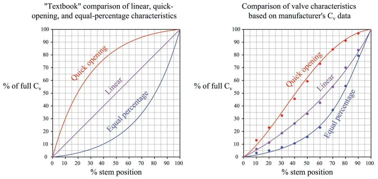
When I look at this characteristic, I separate the bench curve from the plant curve. The bench curve, or inherent characteristic, describes how Cv rises as the plug or disk moves under a fixed pressure drop. In an equal-percentage trim, each equal increment of travel increases Cv by a fixed percentage of the value before it, so the curve starts softly and then climbs faster as it opens.
That matters because real systems rarely keep a constant pressure drop across the valve. As flow rises, pipe friction, heat exchangers, filters, and fittings steal more of the available pressure, so the installed curve can look nothing like the bench curve. The whole point of the equal-percentage shape is to compensate for that and give the controller a more even gain across the working range.
I also think it helps to read “gain” in plain language: it is how sensitive flow is to a small stem movement. Low gain near shut prevents the loop from jumping around; higher gain near full open stops the top end from going dead. That is why this trim is often described as a compromise, but in practice it is often the right compromise. The next question is where that compromise actually pays off.
Where it earns its keep in fluid power systems
In fluid power, the best use cases are the ones where demand changes faster than the piping can stay stable. Steam temperature control is the classic example: a heat exchanger needs tiny, precise changes at low load, then much larger capacity when production ramps up. Cooling-water loops, pressure-reducing stations, gas letdown skids, and boiler feedwater control all show the same pattern when the system pressure drop moves around with operating conditions.
- Steam and hot water heating - the heat transfer curve is non-linear, so a non-linear valve often gives the controller a more usable response.
- Pressure control and letdown - as demand changes, the pressure drop across the valve shifts, so equal-percentage behaviour helps keep flow stable.
- Variable-load water circuits - long pipe runs and changing branch loads make the installed characteristic drift; this trim helps pull it back towards a predictable shape.
- Some hydraulic power circuits - where flow demand changes across a wide span, a smoother low-end response can reduce hunting and overshoot.
I would not use it automatically just because the duty is “control”. If the job is mainly on-off, bypass, or rapid relief, a different trim makes more sense. The right question is always whether the process is non-linear enough to justify the characteristic. That is where a direct comparison helps.
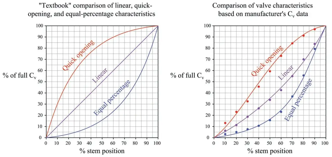
How it compares with linear and quick-opening trims
The easiest way to choose is to compare what each trim does to the loop, not just to the stem position. Equal-percentage behaviour gives the most help when the system becomes less predictable as flow rises. Linear behaviour is simpler and works well when the valve already sees most of the pressure drop. Quick-opening is a different tool altogether; it is meant to get a lot of flow early, which is useful for isolation and relief duties, but not for fine throttling.
| Characteristic | What one stem step does | Best fit | Main risk |
|---|---|---|---|
| Equal-percentage | Each equal step changes capacity by the same percentage of the current flow | Wide turndown, changing pressure drop, steam, gas, and mixed-load water circuits | Can feel too soft if the valve is badly sized or the duty is almost constant-pressure |
| Linear | Each equal step adds roughly the same absolute flow capacity | When the valve owns a large share of the system pressure drop and the installed curve is already close to linear | Can become twitchy near the top end if the valve is oversized |
| Quick-opening | Most of the flow change happens early in travel | On-off, bypass, isolation, relief, and fast dump duties | Poor throttling range and weak control in modulating service |
As a rule of thumb, I tend to favour equal-percentage trim when the valve does less than about 25% of the total full-flow pressure drop. If the valve controls more than that, a linear trim may make more sense. That is not a universal law, but it is a useful filter before you get lost in catalogues. The next step is to make sure the size and authority support the choice.
The sizing mistakes that make it underperform
The most common failure mode is not the trim itself, but a bad match between trim and system. A valve can be described perfectly on paper and still behave badly if the installed pressure profile does not suit it. Two terms matter here: valve authority, which is the share of the total circuit pressure drop that sits across the valve, and vpdd, a practical ratio used to judge how the valve pressure drop changes between low and high flow.
| System clue | What it suggests |
|---|---|
| Valve handles less than about 25% of the full-flow pressure drop | Equal-percentage behaviour often helps linearise the installed curve |
| Valve handles more than about 25% of the pressure drop | A linear trim can become a better fit |
| vpdd roughly 0.20-0.35 | Typical band where equal-percentage trim is often favoured |
| vpdd roughly 0.60-1.0 | Typical band where linear trim is often favoured |
Many industrial trims are quoted around 50:1 rangeability, but that number is not a law of nature. It varies with size, trim style, and manufacturer, and it does not rescue a poor system match. The mistakes I see most often are oversizing, ignoring the minimum controllable flow, assuming a positioner will fix everything, and forgetting about cavitation or noise when the pressure drop gets aggressive.
- Oversizing - the valve spends too much time near closed, where response is hard to tune.
- Ignoring the low end - the loop looks fine at full load and unstable at turn-down.
- Overtrusting the positioner - smart control helps, but it cannot turn a poor hydraulic match into a good one.
- Missing phase-change risks - flashing, cavitation, and erosion can wreck performance regardless of the curve.
Once those errors are off the table, the remaining work is mostly practical specification, which is where many projects either get tidy or get expensive.
What I check before I specify one
If I am sizing a control valve for a real plant, I want the operating envelope before I want the datasheet glamour. The first thing I check is the actual minimum, normal, and maximum flow, because a curve that looks right at one point can behave badly across the rest of the range. Then I look at the pressure drop at each point, because that tells me whether the system is fighting the valve or helping it.
- Operating range - confirm the minimum and maximum duty, not just design flow.
- Pressure profile - check how much pressure the valve really owns at low, normal, and high load.
- Medium behaviour - steam, water, gas, oil, flashing, cavitation, viscosity, and solids all change the decision.
- Actuation - make sure the actuator and positioner can place the stem cleanly without chatter or lag.
- Body and ends - in UK projects, I pay attention early to PN rating, EN compatibility, and maintenance access.
- Noise and wear - if the pressure drop is high, trim choice matters as much as valve size.
A smart positioner can reshape the installed response a bit, but I would still rather start with the right trim than ask the control system to patch a weak hydraulic choice. That becomes even more obvious during commissioning, when the valve meets real process behaviour rather than a sizing spreadsheet.
The details that save time at commissioning
Commissioning is where the theory either holds together or starts leaking. I always want to see where the valve actually sits at the normal operating point. If it is living too close to shut or too close to full open, the loop usually needs a second look. A healthy operating window is usually somewhere in the middle of the travel, where the controller has room to move without becoming twitchy.
- Check real travel - verify that the valve is not spending its life at the extreme ends of stroke.
- Watch low-load behaviour - a good equal-percentage trim should stay calm when demand is small.
- Retune after start-up - once the loop sees the true pressure losses, controller gains often need adjustment.
- Look for hunting - oscillation around 10% to 20% travel is a common sign of mismatch or oversizing.
- Recheck after piping changes - even a modest system modification can change the installed characteristic enough to matter.
That is why I do not treat this choice as a catalog exercise. I treat it as a system decision: the valve, the pipework, the pump or supply source, and the controller all have to agree on what “stable” means. If they do, this trim is one of the most reliable ways to keep a wide-ranging fluid power loop under control. If they do not, the valve will only expose the weakness faster.