A back-pressure regulator is a pressure-control valve that keeps the upstream side of a fluid system at a chosen set point by opening when pressure rises above that point. In practical terms, it is used when a process, return line, sampler or test loop needs steady inlet pressure rather than a simple on-off safety release. I’ll show how it works, where it belongs in a fluid power circuit, how it differs from a pressure-reducing regulator, and what to check before you specify one.
The essentials at a glance
- It controls inlet or upstream pressure, not downstream pressure.
- It normally sits at the end of a line or on a return/bypass path.
- It is not a safety relief valve, so it should not replace overpressure protection.
- Its stability depends on the right pressure range, flow capacity, media compatibility and installation layout.
- Most control problems come from oversizing, missing restriction, contamination or poor system design.
What a back-pressure regulator actually does
The simplest way to think about a back-pressure regulator is as a valve that resists flow until the pressure on its inlet side reaches the set point. Once the upstream pressure climbs high enough, the valve opens just enough to let excess fluid pass through or bypass the circuit, and then it trims back again as conditions change. The goal is stable upstream pressure, not simply limiting pressure in the abstract.
That distinction matters because many people assume the name points to the downstream side. It does not. A back-pressure regulator senses what is happening before the valve, whereas a pressure-reducing regulator senses what is happening after it. In a fluid power system, that difference decides whether you are protecting a process line, a return loop, a sampler or an actuator circuit.
I usually reduce the whole job to one sentence: keep the upstream side steady even when demand, supply pressure or flow path changes. Once that is clear, the mechanical details make a lot more sense, which is exactly what the next section covers.

How it works in a real circuit
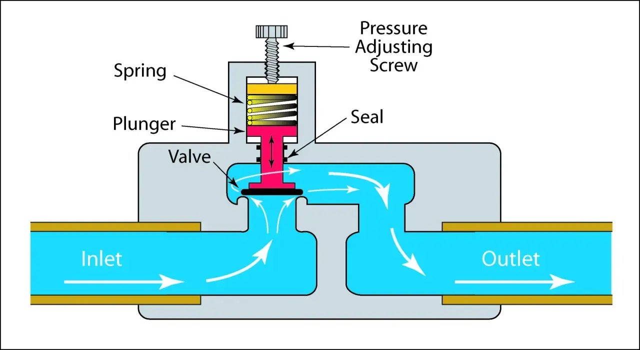
Most back-pressure regulators are built around three basic elements: a sensing element such as a diaphragm or piston, a loading element such as a spring or dome pressure, and a control element made up of a seat and poppet. When the upstream pressure pushes hard enough against the sensing element, the poppet moves off the seat and the valve opens. When pressure falls, the loading force wins and the valve closes again.
In a spring-loaded design, the adjustment screw compresses or relaxes the spring until the balance point matches the desired set pressure. In a dome-loaded or pilot-operated design, a separate control pressure provides that loading force. I tend to see spring-loaded units on simpler duties and pilot-controlled designs when the process needs tighter control, lower hysteresis or remote adjustment.
The important practical point is that the valve needs a real flow path to work against. In many sampling and circulation loops, the back-pressure regulator is paired with a deliberate restriction elsewhere in the circuit so that pressure can build and the valve has something meaningful to regulate. If the system layout gives it no useful pressure drop to manage, the valve can end up wide open and still fail to do the job.
That is why installation is not just a mechanical afterthought. The circuit layout is part of the control strategy, and it shapes how useful the regulator will be once the machine is running.
Why it matters in fluid power and automation
In fluid power, pressure is not just a number on a gauge. It affects flow stability, pump loading, actuator behaviour, test repeatability and even product quality. A back-pressure regulator helps by holding the upstream side in a narrow band instead of letting it wander with every change in demand. That is especially valuable where the process depends on consistent conditions rather than simply maximum throughput.
Here are the places where I see it matter most:
- Recirculation and return lines where a pump or loop needs a controlled head to behave consistently.
- Sampling systems where stable inlet pressure improves repeatability and protects downstream analysers.
- Test stands where pressure stability is needed for valid measurements and comparable results.
- Coating and dispensing circuits where pressure swings can affect atomisation, finish quality or shear-sensitive fluids.
- Liquid circuits near cavitation risk where holding the pressure profile steady can reduce noise, wear and erratic performance.
That last point is easy to overlook. In liquid service, the regulator is not just about pressure control; it is also about keeping the system away from unstable operating regions where flashing, cavitation or chatter can shorten component life. Once you see that, the device stops looking like a niche valve and starts looking like a useful control tool.
Back-pressure regulators and pressure-reducing regulators are not interchangeable
These two valves look similar in catalogues, but they solve opposite problems. A back-pressure regulator holds the upstream side steady. A pressure-reducing regulator holds the downstream side steady. If you swap them casually, the circuit may still flow, but it will not control the pressure where you actually need it.
| Device | What it controls | Typical location | What happens when pressure rises | Best use |
|---|---|---|---|---|
| Back-pressure regulator | Upstream pressure | End of line, return line, bypass leg | Opens to pass or divert more flow and hold the inlet pressure near set point | Recirculation, sampling, test loops, process backpressure |
| Pressure-reducing regulator | Downstream pressure | Beginning of line, supply branch | Closes down to keep outlet pressure at the target | Feeding tools, instruments or pneumatic devices at a lower pressure |
| Pressure relief valve | Maximum system pressure | Protective branch or vessel protection point | Opens at a preset pressure to relieve excess and protect the system | Overpressure safety, not normal process control |
How to choose the right design
When I spec a back-pressure regulator, I start with the process conditions rather than the catalogue first. The pressure range, flow range, media and installation layout tell me far more than a vague “high pressure” or “precision” label ever will. I also write ranges in bar for UK projects, because that is usually the cleanest way to think about the system, even if the final component data sheet uses psi as well.
| Check | What I look for | Why it matters |
|---|---|---|
| Set pressure range | The operating point should sit comfortably inside the adjustment range, not right at the edge | Leaves room for fine tuning and reduces the chance of unstable behaviour |
| Flow capacity | The expected flow should stay well below the valve’s maximum capacity in normal service | If you run too close to the limit, control quality falls away quickly |
| Media and materials | Wetted parts, seals and spring materials must suit the liquid or gas | Prevents corrosion, swelling, sticking and contamination problems |
| Temperature | Full operating temperature, not just room temperature | Seal behaviour, viscosity and spring response all shift with heat and cold |
| Control style | Spring-loaded, dome-loaded or electronically piloted | Higher precision and remote control usually justify a more sophisticated design |
| Maintenance access | Room for gauges, isolation, venting and cleaning | Makes commissioning and service realistic instead of awkward |
Three terms are worth keeping in mind while choosing: droop, lockup and hysteresis. Droop is the change in controlled pressure as flow rises. Lockup is the point where the valve closes tightly as flow falls away. Hysteresis is the gap between opening and closing behaviour around the same nominal set point. If your process is sensitive, these effects matter more than many buyers expect.
My rule of thumb is simple: if the pressure has to stay very steady across a wide flow range, I would lean towards a more precise design rather than trying to force a basic spring unit to do a precision job. The next section shows why a good valve can still perform badly if the system layout is wrong.
Installation mistakes that make a good regulator look bad
Most poor regulator performance is not caused by the valve alone. It is caused by the circuit around it. A back-pressure regulator can only control what the system allows it to control, so installation choices have a direct effect on stability, response and service life.
- Putting it in the wrong location can make it regulate the wrong side of the system or fight against another device.
- Leaving out the necessary restriction can leave the valve open with little or no real pressure control.
- Oversizing the valve often causes hunting or chatter because the valve becomes too sensitive for the actual flow.
- Using the wrong spring range can force the valve to operate at the edge of its adjustment window.
- Ignoring contamination can damage the seat, foul the poppet or make the valve stick.
- Routing liquids where vapour can form can trigger cavitation, noise and erratic control.
- Placing two pressure controllers in series without flow resistance can create an unstable fight between them instead of useful regulation.
If the valve seems noisy or unstable, I do not start by blaming the hardware. I start by checking whether the layout, flow path and operating point make sense. That mindset saves a lot of time because the root cause is often in the circuit, not the regulator body. With that in mind, there are a few commissioning checks that catch most problems before they become expensive.
The checks that catch problems before commissioning
Before I sign off a back-pressure loop, I run through a short list. It is not glamorous, but it prevents a lot of avoidable rework.
- Confirm that the valve is controlling the upstream side you actually care about.
- Check that the set point sits well inside the usable adjustment range.
- Compare the expected flow with the valve’s capacity so you are not running near its limit.
- Verify material compatibility with the process fluid, cleaning regime and temperature.
- Make sure gauges, vents and isolation points are accessible after installation.
- Test the loop at minimum and maximum demand so you can see whether the control remains stable.
When those checks pass, the regulator usually behaves the way the drawing promised. When they fail, the fix is often to change the circuit strategy rather than to keep chasing a different valve. That is the practical answer I would give anyone building a new fluid power or process loop: choose the control philosophy first, then select the hardware that fits it.