In fluid power systems, the inlet side is where many problems start, and the available suction margin often decides whether a pump runs quietly or begins to cavitate. Pump suction head is the practical way of describing that pressure condition at the suction port, usually as a head in metres rather than a raw pressure reading. In this article, I break down what it means, how it relates to NPSH, how to estimate it, and what to change when the margin is too small.
The inlet margin decides whether the pump runs cleanly or cavitates
- Suction head is best treated as an inlet-side margin, not just a pressure number.
- Positive suction head helps the pump; suction lift takes margin away before the impeller even starts working.
- NPSH is the key check for cavitation risk, so the available margin must stay above the pump’s requirement.
- Long suction runs, hot liquids, and high flow rates all make the inlet condition worse.
- The fastest improvements usually come from layout changes, lower losses, and better pump selection, not from last-minute control tweaks.
What the suction side really tells you
When I look at a pump, I start with the inlet because that is where the machine either gets fed properly or begins to struggle. Positive suction head means the liquid level sits above the impeller inlet, so gravity is helping the pump. Suction lift is the opposite case, where the pump has to draw liquid from below its centreline, which instantly reduces the available pressure at the eye of the impeller.
That distinction matters because the number on a gauge is not the whole story. The useful quantity is the pressure margin available at the suction port after pipe losses, elevation changes, and liquid vapour pressure are accounted for. NPSH, or net positive suction head, is the margin between the liquid at the inlet and the point where vapourisation starts.
| Term | What it means | Why I care about it |
|---|---|---|
| Suction head | The liquid level is above the impeller inlet. | It gives the inlet a helpful pressure cushion. |
| Suction lift | The liquid level is below the pump centreline. | It removes margin and makes cavitation more likely. |
| Inlet pressure | The pressure available where the suction pipe meets the pump. | This is the real operating condition, not just the tank reading. |
| NPSHa | The net positive suction head available from the system. | It must exceed the pump’s requirement at the duty point. |
| NPSHr | The net positive suction head required by the pump. | This comes from the pump curve and changes with flow. |
| Delivery head | Discharge pressure minus suction pressure. | Useful for system sizing, but not the same as inlet safety. |
I also keep one simple conversion in mind: 1 bar is roughly 10.2 m of water head. That is why these calculations are usually easier to reason about in metres of head than in mixed pressure units. In open systems, atmospheric pressure helps feed the pump; in break-tank booster sets or pressurised installations, the inlet margin comes from whatever the system can actually deliver after losses. Once that language is clear, the cavitation question becomes much easier to answer.
Why low inlet pressure turns into cavitation
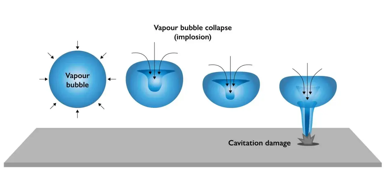
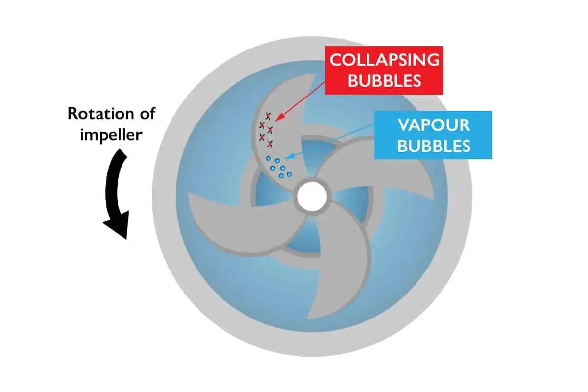
Cavitation starts when local pressure falls below the liquid’s vapour pressure. Bubbles form, then collapse violently as pressure recovers inside the pump. The result is noise, vibration, pitting, and a steady loss of performance that often looks like a mechanical fault long before anyone checks the suction line.
Hot liquids make this worse because vapour pressure rises with temperature. That is why a pump that behaves well on cold water can become unstable once the process fluid warms up, even if nothing else in the system changes. The theoretical limit is also easy to forget: in a perfect vacuum, water could be lifted about 10.33 m, but real installations never get close to that because friction, vapour pressure, and mechanical losses eat into the margin.
- Noise that sounds like gravel or marbles in the casing.
- Vibration that gets worse as flow rises.
- Pitting on the impeller and casing from bubble collapse.
- Flow instability that shows up as poor repeatability in the process.
- Lower capacity than the curve suggests at the same speed.
I treat those symptoms as a suction-side warning, not a reason to blame the motor first. Once cavitation begins, the next step is usually to find where the margin disappeared, which is why I always move from symptoms to calculation rather than guessing.
How I estimate the margin in practice
The method is less mysterious than it sounds. I want three things: the actual inlet pressure at the pump, the suction-side losses, and the pump’s required margin at the operating flow. In practice, that means checking the installed pipework, the liquid temperature, and the pump curve together instead of reading any one of them in isolation. A gauge reading by itself is useful, but it is not enough if you do not know how much of that pressure is already being consumed before the liquid reaches the impeller.
- Measure or estimate the pressure available at the suction port.
- Subtract friction losses from the suction pipe, fittings, strainers, and valves.
- Account for vapour pressure at the actual operating temperature.
- Compare the result with the pump’s NPSHr at the duty point.
- Leave a safety margin, especially if level, temperature, or flow can drift.
A worked example makes the logic obvious. At 30°C, water vapour pressure is about 0.43 m. If suction-side friction loss is 1 m and the pump needs 3 m NPSHr at the operating flow, the minimum inlet pressure works out at 4.43 m. Add a 0.5 m safety margin and I would want the system to stay above 5 m in service. That example is for water, but the method is the same for other fluids: the hotter and more volatile the liquid, the less forgiving the inlet side becomes. In other words, the margin is not a fixed number, it moves with the process.
What improves suction conditions fastest
When the margin is thin, I do not start with controls. I start with the layout. The quickest gains usually come from reducing losses before the pump has to do any real work. That is the part many teams underestimate, because it is less glamorous than software tuning but far more effective when the inlet is starved.
| Change | What it does | Trade-off |
|---|---|---|
| Shorten or straighten the suction run | Reduces pressure loss before the inlet | May require layout changes |
| Use a larger suction line | Lowers velocity and friction loss | More space and higher pipe cost |
| Lower the pump relative to the liquid level | Turns suction lift into flooded suction | Can mean a mechanical redesign |
| Clean strainers and remove unnecessary restrictions | Restores lost inlet pressure | Only helps if blockage was the issue |
| Reduce speed or flow | Lowers NPSH demand and friction loss | Output drops, so it is not a structural fix |
| Select a pump with lower NPSHr | Builds in more inlet tolerance | May increase cost or change efficiency |
I rarely trust a small control tweak to solve a badly designed suction line. If the pipework is starved, noisy, or full of air, the system needs a physical fix first. That is why layout decisions made at design stage usually matter more than tuning later, especially on fluid power projects that must stay stable across changing duty points.
How pump choice changes the result
Not every pump behaves the same at the inlet. For centrifugal pumps, I pay close attention to the NPSHr curve, the operating speed, and how far the duty point sits from the best efficiency point, or BEP. BEP is simply the point where the pump runs most efficiently, and it is usually the place where internal hydraulic losses are least troublesome.
For challenging suction conditions, a pump with a lower NPSHr, a larger suction eye, or a better-suited impeller can make a real difference. Many end-suction designs are built specifically to improve suction behaviour, but they are still non-self-priming, which means they cannot purge air and start on a dry suction line, so they still need an inlet arrangement that can actually feed them.
- Lower NPSHr gives more tolerance when the suction line is not ideal.
- Lower speed usually reduces suction demand, but it may require a larger pump or a different duty point.
- Flooded suction is easier to live with than suction lift, because the pump starts with positive pressure already available.
- Positive-displacement pumps still need inlet protection, even though their suction behaviour is handled differently from centrifugal machines.
If I am matching a pump to a fluid power system that will see temperature swings, intermittent operation, or a long suction run, I would rather choose a slightly more forgiving pump than gamble on a tight margin. That choice is often cheaper than fixing chronic cavitation later, and in practice it usually gives better uptime as well.
What I check before commissioning a system
Commissioning is where many inlet problems reveal themselves. A system can look fine on a cold start and still fail once the tank level drops, the liquid warms up, or a strainer loads up with debris. I check the suction side before I trust the rest of the loop, because that is where a quiet installation either proves itself or exposes its weak point.
- Confirm the liquid level under worst-case operating conditions, not just at fill level.
- Make sure isolation valves on the suction side are fully open and correctly positioned.
- Check for air ingress at joints, seals, and threaded connections.
- Inspect strainers, filters, and any fittings that create unnecessary restriction.
- Verify that the suction pipe is sized and routed to keep losses low.
- Measure inlet pressure close to the suction port if the application is critical.
- Trend the reading over time, because a slow drop is often more useful than one snapshot.
In connected plants, a simple pressure transmitter on the suction line is often the most underrated sensor on the skid. When that signal drifts, it usually tells you more about the health of the installation than a dozen assumptions about the pump itself. That is the kind of early warning I want before the process starts paying for downtime, and it is one of the easiest places to add meaningful monitoring.
The inlet side is where reliability is won
If I had to reduce the whole topic to one rule, it would be this: protect the inlet first, then worry about everything else. A pump with decent suction conditions, sensible pipework, and enough operating margin is far easier to live with than a machine that is permanently fighting its own inlet.
- Watch the available margin, not just the headline pressure.
- Compare the actual operating point with the pump’s NPSHr curve.
- Treat temperature rise, suction losses, and air ingress as real design inputs.
- Use monitoring to catch slow drift before it becomes damage.
That approach keeps fluid power systems quieter, more stable, and more predictable in day-to-day service. If the suction side is right, the rest of the pump usually has a fair chance to do its job.