Hydraulic and pneumatic systems make sense once you reduce them to one simple relationship: how much pressure acts on how much area. The basic idea behind pressure times area is what turns line pressure into a usable push on a piston, clamp, press, or gripper. In fluid power, that number is the difference between a machine that behaves predictably and one that looks fine on paper but stalls under load.
The force estimate depends on the area you actually use
- Force comes from pressure acting on effective area, so bore size matters as much as the pressure setting.
- Use one unit system before multiplying: Pa with m², bar with cm², or MPa with mm².
- Hydraulics usually produce far more force than pneumatics because the operating pressure is much higher.
- The retract stroke of a double-acting cylinder is weaker because the rod reduces the working area.
- Real machines lose some output to friction and pressure drop, so the calculated figure is a starting point, not a guarantee.
How the force equation works in fluid power
The calculation itself is straightforward: force equals pressure multiplied by area. In SI terms, that gives newtons from pascals and square metres, which is the cleanest way to think about it if you are doing a full engineering check. In day-to-day fluid-power work, though, I usually see the same relationship written with bar, square centimetres, or square millimetres because those units are faster to handle on the shop floor.
This gives force, not energy. A cylinder can generate the same static force at a given pressure whether its stroke is short or long; the stroke mainly changes how far the actuator can travel and how much fluid it needs. That is an important distinction, because people often assume a longer stroke somehow means more force. It does not.
The same math applies to hydraulics and pneumatics, but the operating conditions are very different. Hydraulic systems often work in the tens or hundreds of bar, so a compact cylinder can produce a serious push. Pneumatic systems are usually much lower in pressure, which is why they are lighter, cleaner, and simpler, but also less force-dense and easier to disturb when the load changes.
For a quick comparison, a 10 cm² actuator at 6 bar produces about 600 N. The same area in a hydraulic circuit at 160 bar produces about 16,000 N. That gap is why the fluid-power choice matters long before you reach the final machine design.
Once that relationship is clear, the real work is keeping the units honest.
The units that keep the calculation honest
In UK engineering, I usually expect to see bar on the pressure gauge, millimetres on the drawing, and newtons or kilonewtons on the machine spec. The calculation only works cleanly when those units are made consistent before the multiplication happens.
| Unit set | Practical shortcut | When I use it |
|---|---|---|
| Pa and m² | F = P × A | Base SI, useful for formal calculations, but awkward for small parts |
| bar and cm² | F(N) = bar × cm² × 10 | Very convenient for UK hydraulic work and quick checks |
| MPa and mm² | F(N) = MPa × mm² | Handy when drawings and stress figures are already in metric SI |
One shortcut I use often is this: 1 bar acting on 1 cm² gives 10 N. It is not a replacement for proper unit discipline, but it is a fast way to sanity-check a figure before you trust it. With that out of the way, a worked example makes the relationship much more concrete.

A worked cylinder example shows how quickly the numbers grow
Take a hydraulic cylinder with a 63 mm bore running at 160 bar. The piston area is about 3,117 mm², so the extend force comes out at roughly 49.9 kN. That is enough to move a genuinely heavy load, even though the actuator itself is still fairly compact.
| Condition | Area used | Force at 160 bar |
|---|---|---|
| Extend stroke | 3,117 mm² | 49.9 kN |
| Retract stroke with a 36 mm rod | 2,099 mm² | 33.6 kN |
The difference between those two figures is what catches people out. If a machine needs the same clamping or pressing force in both directions, the retract side may disappoint unless the bore is larger, the rod is smaller, or the circuit pressure is higher. That is why the effective area matters more than the nominal cylinder size printed on the datasheet.
That example also shows why I never treat “cylinder size” as a complete answer. The rod side changes the result, and that leads straight into the part of the calculation that is easiest to overlook.
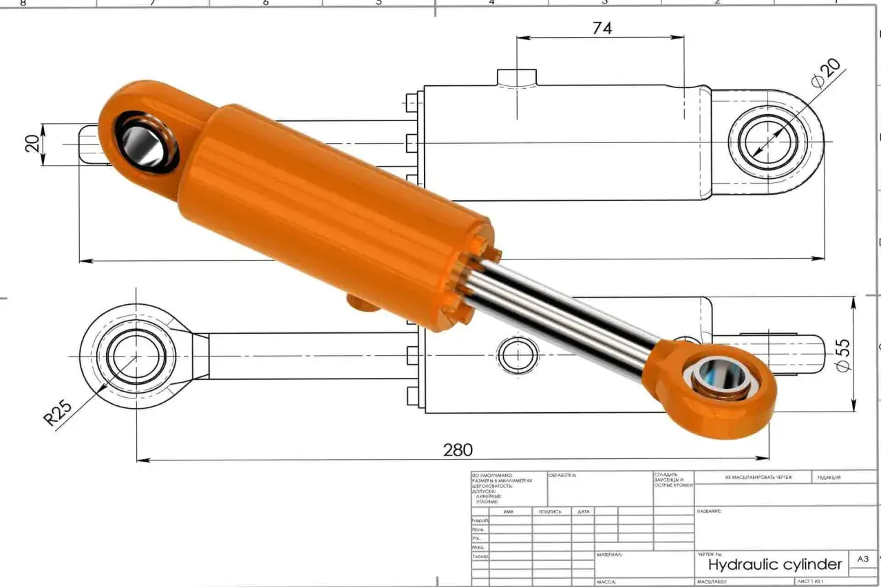
Why the rod side gives less force
On a double-acting cylinder, the rod occupies part of the piston face during retraction, so the working area is smaller. That smaller annulus area is why retract force is lower even when the system pressure stays exactly the same. In practical terms, the bore controls the push force, while the rod diameter controls how much of that force survives on the return stroke.
- Bore size controls the available area and therefore the maximum push force.
- Rod diameter reduces the pull force on the return stroke.
- Stroke length does not change static force, but it does change fluid volume, cycle time, and pump or compressor demand.
- Seal drag and side loading can reduce the force you actually see at the machine.
I see this mistake often in early layouts: someone optimises for stroke length and assumes the force figure will improve with it. It will not. Stroke is about travel; area is about force. Keep those two jobs separate, and the sizing discussion becomes far more accurate.
Once the geometry is clear, the next risk is not the physics but the shortcuts people take when applying it.
Common mistakes that make the result look better than it is
I see the same errors again and again, and they all lead to overconfidence. The calculation is not fragile, but it is easy to misuse.
- Using the full bore area for both strokes when the rod side is smaller.
- Ignoring pressure drop across valves, hoses, manifolds, filters, and fittings.
- Assuming pump or compressor pressure is the same as pressure at the actuator.
- Forgetting friction, seal drag, and mechanical losses in the linkage or guides.
- Mixing bar, psi, mm², in², or m² without converting first.
The most dangerous mistake is the one that hides inside a spreadsheet. If the units are inconsistent, the number can still look plausible, which is exactly why bad sizing survives so many design reviews. In production equipment, that turns into a weak clamp, a sluggish press, or a cycle time that misses target. The force figure is only useful when it reflects the real circuit, not an idealised one.
That matters even more once the calculation moves from a worksheet into a live machine.
What the calculation means for machine design and connected systems
For machine builders, the force estimate is not just academic. It shapes cylinder selection, mounting style, valve sizing, hose bore, relief valve setting, and the control strategy in the PLC. In a press, a clamp, or a palletising cell, I want the actuator to reach the target force with margin, but not so much oversizing that I waste energy, increase shock loads, or slow the cycle.
This is also where industrial automation and connected monitoring help. A pressure transducer can tell you whether the system is reaching the expected pressure, and that lets you infer whether the actuator is likely producing the intended force. But I would treat that as verification, not as a replacement for the sizing calculation. Sensors show what the machine is doing; the pressure-and-area relationship tells you whether the design makes sense in the first place.
In smart manufacturing, that distinction is practical rather than theoretical. Connected systems can spot drift, blocked filters, or a failing seal earlier than manual checks can, but only if the original force target was realistic. The last step is the short check I use before I trust any figure.
The checks I would make before I sign off a force figure
Before I accept a cylinder size or clamp force, I run through a short checklist. It takes minutes, and it saves expensive redesigns later.
- Convert pressure and area into one unit system before multiplying.
- Check both extend and retract forces, not just the stronger stroke.
- Subtract realistic losses for friction and pressure drop.
- Compare the result with the load, not with a vague target.
- Leave margin for wear, temperature change, and supply variation.
If you want a reliable rule of thumb, use the calculation to find the force you should expect, then compare it with what the machine actually needs at the actuator face. That is the difference between a tidy number on paper and a fluid-power system that performs consistently on the line.