What matters most before you start calculating
- Flow rate is usually calculated from volume over time, area times velocity, or pump displacement times speed.
- In hydraulics, flow drives speed and pressure drives force; confusing the two leads to bad sizing decisions.
- Actual pump delivery is lower than theoretical flow once volumetric efficiency and leakage are included.
- Throttle valves and orifices can shape flow, but they usually trade efficiency for control.
- Unit mistakes are the fastest way to get a result that looks precise and is still wrong.
Why flow rate is the number that actually moves a machine
When I look at a hydraulic circuit, I usually start by asking a very simple question: is the problem speed, force, or both? If a cylinder is too slow, more pressure will not automatically fix it. If the load is too heavy, more flow will not create force on its own. That distinction matters because flow rate shows up in actuator speed, cycle time, cooling load, and pump sizing, while pressure tells you what the machine can push against.
In real installations, especially where bar and L/min are the normal working units, flow is the practical number that tells you whether a line will keep up with production. A system can look perfectly acceptable on paper and still feel sluggish if the available flow drops once the oil warms up, a filter starts loading, or a valve introduces more loss than expected. Once you treat flow as the speed variable, the formulas fall into place much more cleanly.
The formulas I reach for first
For day-to-day work, I keep a short list of formulas close at hand. They cover most pump, cylinder, and valve questions without forcing you into a full simulation model every time. The key is to keep the units aligned before you trust the answer.
| Formula | What it tells you | Where I use it | Practical note |
|---|---|---|---|
| Q = V / t | Volumetric flow from volume and time | Tank fill checks, leakage tests, test rigs | Keep the volume and time units compatible; 1 L/min is 1/60 L/s. |
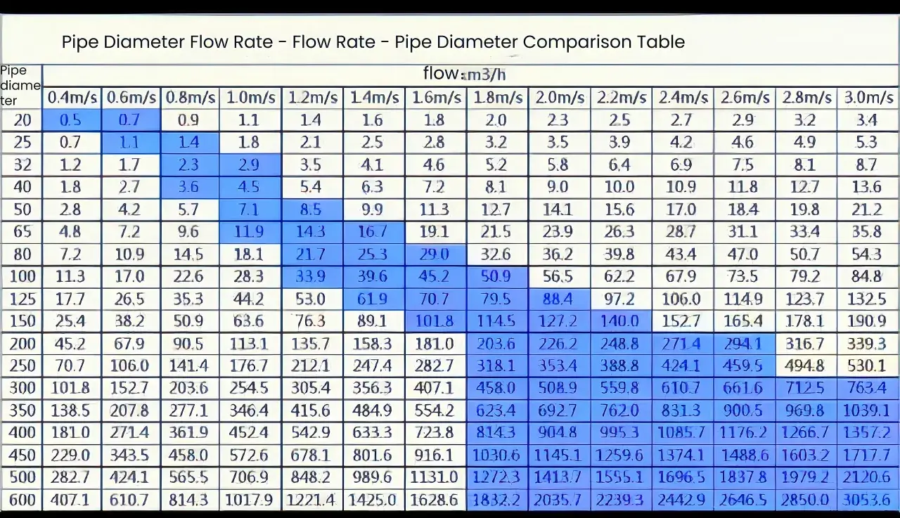
| Q = A × v | Flow from area and fluid velocity | Cylinder speed, pipe sizing | Use the active area. On retract stroke, use annulus area, not full bore area. |
| Q = (D × n) / 1000 | Theoretical pump flow | Pump selection and speed changes | D is in cm³/rev, n is in rpm, and Q comes out in L/min. |
| Q_actual = Q_theoretical × ηv | Actual flow after volumetric losses | Realistic sizing | Leakage grows with pressure, wear, and temperature. |
| P(kW) = p(bar) × Q(L/min) / 600 | Hydraulic power | Motor sizing, heat checks | Double pressure or flow and the power demand doubles. |
| F ≈ p(bar) × A(cm²) × 10 | Cylinder force | Load checks | This is force, not speed. Do not swap it with the flow equation. |
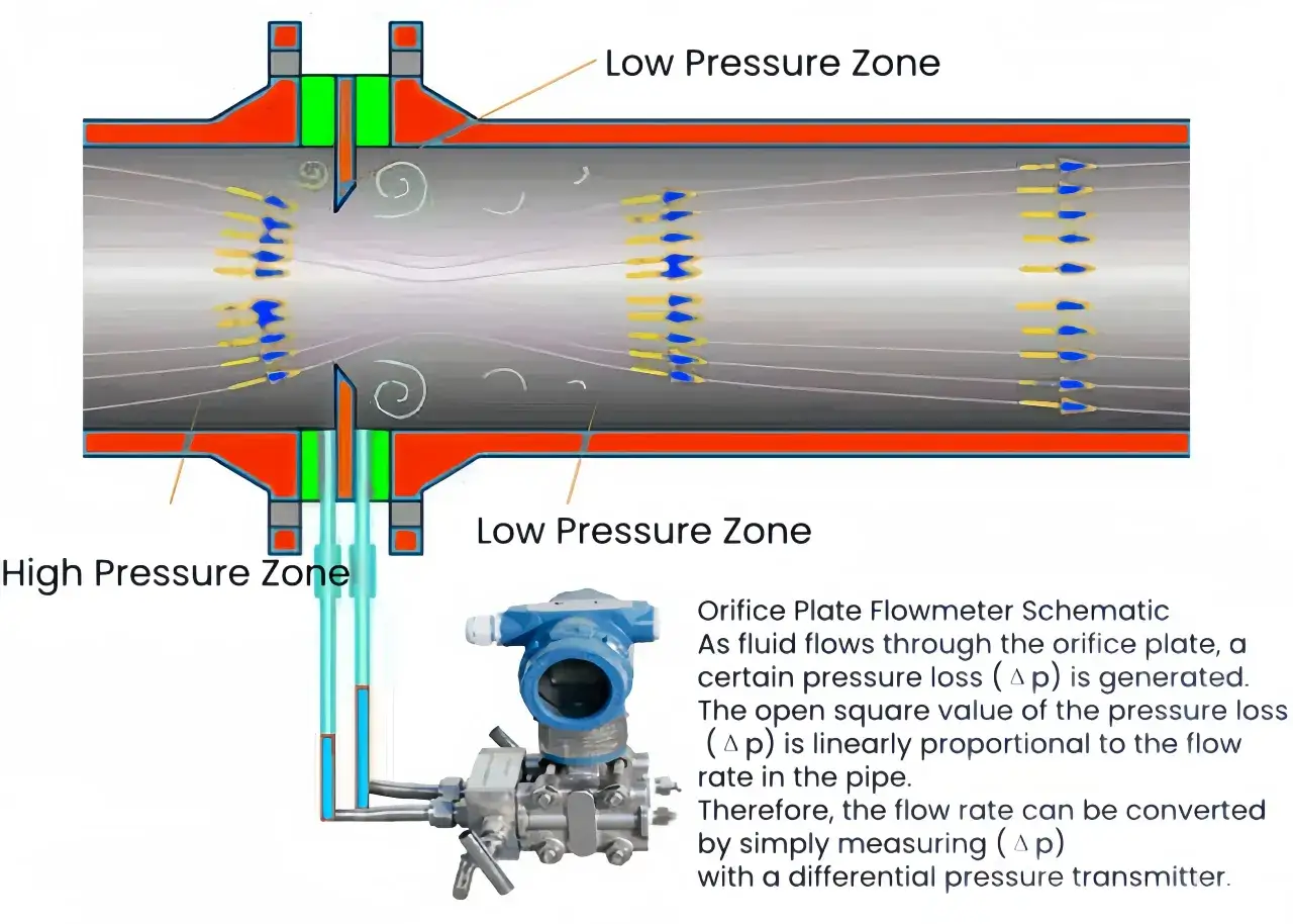
| Q ∝ A√Δp | Flow through a restriction | Orifices and throttling valves | Useful for understanding behaviour; exact sizing depends on the discharge coefficient and geometry. |
If you prefer pure SI, the two conversions I use most are simple: 1 bar = 100,000 Pa and 1 L/min = 1.6667 × 10⁻⁵ m3/s. Get those wrong and the rest of the maths will look believable for all the wrong reasons. With those identities in hand, the numbers in a real circuit become much easier to trust.
How I calculate flow in a real hydraulic circuit
I prefer to test the formulas against a real machine rather than leave them floating in theory. A few straightforward examples usually expose whether the system is underfed, over-restricted, or simply being judged with the wrong units.
Estimating pump delivery
Take a 32 cm³/rev pump running at 1,450 rpm. The theoretical flow is 46.4 L/min. If volumetric efficiency is 92%, actual flow drops to 42.7 L/min. That gap matters because nameplate flow is not what the machine sees once pressure, leakage, and temperature are part of the picture. I would trust the 42.7 L/min figure for cycle-time checks and reserve the higher number for a theoretical ceiling.
Turning flow into cylinder speed
Now use a 50 mm bore cylinder. The piston area is 19.63 cm², so 20 L/min gives about 170 mm/s extension speed. If the rod is 25 mm, the annulus area falls to 14.73 cm², and the same flow produces about 226 mm/s on retract. For a 400 mm stroke, that works out to roughly 2.35 seconds extend and 1.77 seconds retract. The detail that matters here is simple: retract speed is higher because the active area is smaller.
Read Also: Air Pump vs. Air Compressor - Which Do You Really Need?
Checking the power budget
At 80 bar and 25 L/min, hydraulic power is 3.33 kW. If the pressure rises to 160 bar at the same flow, power becomes 6.67 kW. That is why I never look at pressure in isolation when I am sizing a motor, cooler, or hose set. A pressure setting can look harmless until you multiply it by a genuine operating flow and see the power demand jump in line with it.
These examples are deliberately plain. In practice, simple numbers are easier to verify against gauges and cycle time than elegant formulas that nobody on site can sanity-check quickly. Once you can do these calculations confidently, most spec sheets stop feeling opaque and start behaving like useful evidence.
How to change flow without damaging the circuit
There are several ways to manipulate flow, but they do not all behave the same way. Some approaches change flow at the source, others waste excess flow as heat, and a few improve control while keeping losses manageable. The best option depends on whether you are after system-wide efficiency, local speed trimming, or synchronised movement.
| Method | What it changes | Best for | Main trade-off |
|---|---|---|---|
| Change pump speed | Whole-system flow | Variable-duty equipment with an electric drive | Needs a suitable motor, drive, and suction design. |
| Variable displacement pump | Whole-system flow on demand | Efficient control under varying loads | Higher cost and more complex control hardware. |
| Throttle or needle valve | Local branch flow | Simple speed trimming on a single actuator | Creates pressure drop, heat, and wasted energy. |
| Pressure-compensated flow control | More stable branch flow | Maintaining actuator speed as load changes | Better than a plain throttle, but still not lossless. |
| Flow divider | Flow split between branches | Synchronising two cylinders or motors | Extra pressure drop and added component complexity. |
| Parallel circuit arrangement | Total inlet flow and branch distribution | Multiple actuators needing independent movement | Branch flow splits by resistance, not by wishful thinking. |
| Series circuit arrangement | Same flow through each element | Simple staged motion | Pressure is shared across the load path, so force margin can shrink quickly. |
When I want efficiency, I try to change flow at the source. When I only need to trim one actuator, I may accept a valve loss. That trade-off is the whole game: use the least wasteful method that still gives you the control you need. From there, the question becomes less about math and more about avoiding predictable mistakes.
The mistakes that give you wrong answers
Most bad flow calculations fail for boring reasons, not advanced ones. The same few errors keep appearing because they are easy to make under pressure and easy to miss if you only check the final number.
- Mixing L/min with m3/s, or cm² with mm², without converting every term first.
- Using full bore area for a retract stroke instead of the annulus area around the rod.
- Assuming nameplate pump flow is the same as delivered flow at working pressure.
- Ignoring oil temperature, which changes viscosity, leakage, and valve behaviour.
- Treating pressure as a direct way to increase flow in a fixed-displacement pump circuit.
- Forgetting pressure losses in hoses, fittings, filters, coolers, and manifolds.
- Comparing pneumatic flow figures without checking whether they are actual, normal, or standard values.
The last point matters more than many engineers admit. In compressed-air systems, two flow numbers can look identical and still refer to different reference conditions. If you do not check that detail, you can end up comparing apples to a very expensive orange. Once the unit discipline is fixed, the remaining error usually comes from leakage or pressure loss, which is much easier to diagnose.
The checklist I use before I sign off a flow change
When a circuit needs a change, I run a short checklist before I approve it. It is not complicated, but it catches most of the avoidable mistakes before they become commissioning problems.
- Define the working units first and keep them consistent through the whole calculation.
- Work out the theoretical flow from pump displacement, speed, or actuator geometry.
- Apply volumetric efficiency, leakage, and any known restriction losses.
- Check cycle time, force, and power together instead of treating them as separate questions.
- Verify pressure drops across valves, hoses, filters, and coolers at the real duty point.
- If the system is pneumatic, confirm whether the quoted flow is actual, normal, or standard.
- If live sensors are available, compare the calculation against operating data at temperature, not just during idle testing.
That last step is where modern instrumentation helps a lot. A pressure and flow trend from a connected machine often tells you more than a single spot reading, especially when wear, contamination, or valve drift is creeping in slowly. When the maths and the live data disagree, I trust the measured trend long enough to explain the gap, then I fix the cause rather than the symptom.