Hydraulic industrial cylinder mounts are not a minor accessory; they decide how force enters the machine, how much side load reaches the seals, and whether the cylinder can tolerate real-world misalignment. In fluid power systems, I treat the mount as a structural choice, not a catalogue afterthought. This article breaks down the main mounting styles, how to match them to push, pull and oscillating motion, and what to check during installation so the assembly survives beyond first commissioning.
The mount choice should follow the load path, not the other way around
- Fixed mounts suit straight-line force transfer; pivoting mounts suit motion that swings through an arc.
- Flange and tie-rod styles are usually the cleanest answer for push or pull loads, provided the frame is rigid.
- Foot mounts need strong guidance because they create a turning moment around the mounting bolts.
- Trunnions and clevises are forgiving only when the pin geometry and bearing support are correct.
- Most early failures come from side load, poor alignment, or under-designed fasteners, not from the cylinder bore itself.
Why the mount determines how the cylinder behaves
The mount decides whether the cylinder works in pure line-of-action or spends its life fighting a bending moment. That matters because the rod, gland, pins and bearings are designed to take axial force first; once the machine starts loading them sideways, wear accelerates quickly. In many UK industrial builds, especially those using metric cylinders aligned to ISO 6022-style dimensions, the nominal pressure and bore size are only half the story: the mount has to suit the motion path, the available frame stiffness and the real duty cycle.
I have seen otherwise decent cylinders fail early simply because the linkage was forced to correct for poor machine geometry. When the frame guides the load, the cylinder only provides thrust. When it does not, the seals and rod bearings become the alignment system, and that is usually a losing trade.
ISO 6022 is useful here because it frames the cylinder around interchangeable mounting dimensions for 25 MPa, or 250 bar, service. That does not remove the need for engineering judgement; it just means the mount has to be chosen with the machine’s motion in mind, not just its catalogue footprint.
That is why the next question is not “which cylinder looks strongest?” but “which mounting family matches the way this machine actually moves?”
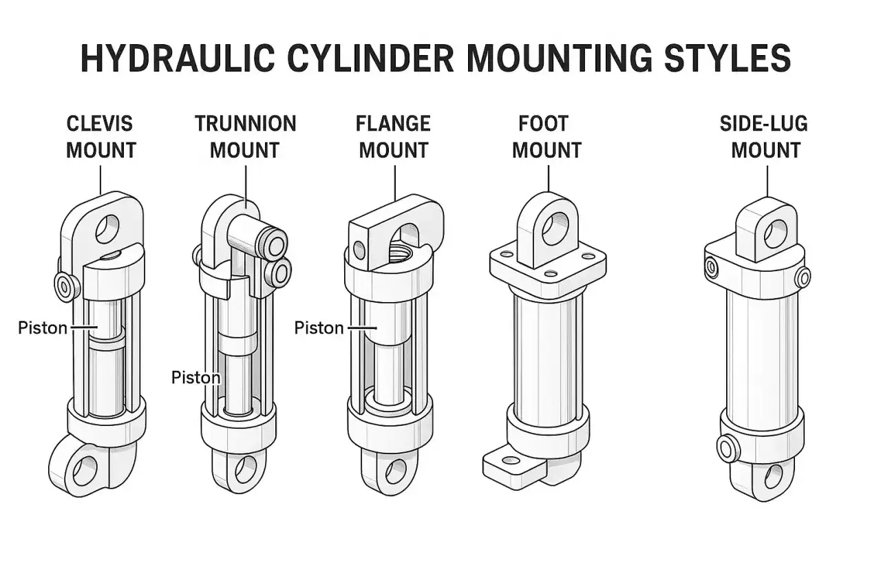
The main mount families and where each one fits
When I compare mount options, I start with the job the cylinder is expected to do, then I narrow the field by movement, space and service access. The table below is the quickest way to separate a sensible choice from one that only looks compact on paper.
| Mount style | Best fit | What it does well | What to watch |
|---|---|---|---|
| Flange mount | Straight-line thrust, either push or pull depending on which end is fixed | Clean force transfer and good rigidity when the frame is stiff | Choose the end carefully; the wrong orientation can put the rod in the wrong stress regime |
| Foot mount | Base-mounted machines, presses and compact installations | Simple layout and easy to understand in service | Creates a turning moment around the bolts, so the load must be guided elsewhere |
| Tie-rod mount | Limited-space industrial builds and standard metric cylinder packages | Compact, familiar and easy to integrate into a machine frame | Nuts and fasteners have to be torqued correctly; alignment still matters |
| Clevis mount | Pivoting linkages and compact oscillating motion | Handles angular movement cleanly when both ends pivot in one plane | Pin centres must stay parallel and the working arc must be unobstructed |
| Trunnion mount | Single-plane swing motion, longer strokes and larger machine members | Absorbs centreline forces well when the bearings are properly supported | Trunnion pins are for shear, not bending; bearing blocks need to be rigid and lubricated |
| Spherical bearing mount | Motion that may wander slightly off true plane | More forgiving when the rod path is not perfectly straight | Costs more and still needs correct lubrication and angular capacity |
The practical distinction that matters most is this: flange and tie-rod styles are usually better for straight-line force transfer, while clevis, trunnion and spherical arrangements are there to accommodate motion, not to hide bad alignment. Once that family decision is clear, the next filter is how the cylinder actually moves under load.
How I match the mount to motion, force and stroke
I usually separate selection into three questions. First, is the load mainly push or pull? Second, is the machine member moving in a straight line or tracing an arc? Third, does the frame itself guide the load, or is the cylinder being asked to do that job?
Straight-line force transfer
For straight-line applications, flange and tie-rod patterns are often the cleanest answer. If the main force is compressive, I favour the cap-end arrangement; if the load is mainly in tension, the head-end arrangement usually makes more sense. The point is not to be clever. It is to keep the piston rod working in the stress condition the machine actually creates.
Motion that swings or arcs
Once the machine member moves through a curve, fixed mounts start to work against you. In those cases, clevis and trunnion patterns earn their keep because they allow the cylinder to pivot instead of forcing the rod to bend. If the motion can wander to either side of the true plane, I would step up to a spherical bearing rather than pretending a basic clevis will cover the extra angular error.
Stroke length and side load
Longer stroke does not automatically mean a different mount, but it does increase the penalty for poor guidance. A short, well-guided stroke can survive on a simpler layout. A long stroke with a flexible frame usually cannot. If the load path is not properly supported, the cylinder begins to absorb side load, and the wear pattern shows up first in the rod seal and gland bearings.
My rule is simple: if the machine needs the cylinder to correct alignment errors, I go back and fix the machine geometry instead of pretending the mount can compensate for it. That leads directly into installation, because even the right mount can be ruined by sloppy assembly.
Installation details that prevent side load and looseness
Most of the expensive mistakes happen here, not in the selection stage. I would rather see a modest cylinder with the right bolts, pins and alignment than a premium cylinder bolted on badly.
- Use proper fasteners. Choose the largest high-tensile alloy steel socket head cap screws that fit the mounting holes, then torque them to the manufacturer’s recommendation.
- Use thrust keys or dowels where the mount needs location. Side-mounted cylinders should not rely on bolt friction alone to resist the main load.
- Align flange mounts before pinning. The flange can be used as a pilot during alignment, then drilled for pins or dowels to stop shifting.
- Keep trunnion supports rigid. Bearing blocks should be accurately aligned, with minimal clearance and proper lubrication, so the trunnion is not bent by the structure.
- Check clevis geometry through the full arc. Pin centrelines should stay parallel, and the cylinder must swing freely without hitting adjacent parts.
- Keep ports clean until final connection. Contamination during installation is a classic way to turn a good build into a maintenance problem.
One detail I see missed again and again is access. If you cannot reach the pins, grease points or fasteners without dismantling half the machine, the mount is already working against the maintenance team. On connected or sensorised equipment, I also leave room for wiring, transducers and switch brackets so the mount does not become the first bottleneck in service.
Once those installation basics are right, the choice of material and finish starts to matter more than most people expect, especially in British plants with humidity, washdown or outdoor exposure.
Materials and maintenance for UK industrial environments
A mount that looks fine in a dry showroom can behave very differently in a damp factory, a coastal site or a washdown area. In the UK, I assume moisture and condensation unless the application clearly proves otherwise. That changes what I look for in pins, brackets, protective coatings and exposed hardware.
For normal indoor duty, standard steel hardware with a sensible protective finish is usually enough. For harsher environments, I pay more attention to corrosion resistance, protective covers and the condition of exposed rod surfaces. The rod itself may not be the mount, but if corrosion or contamination attacks the end hardware, the whole assembly suffers.
| Environment | What I would specify | Why it matters |
|---|---|---|
| Dry indoor automation cell | Standard high-grade hardware and routine inspection | Low corrosion risk, so alignment and torque control matter most |
| Humid plant or washdown area | Corrosion-resistant finish, protected pins and better sealing discipline | Prevents seized hardware, rust staining and premature wear |
| Outdoor or stored equipment | Port protection, rust inhibitor on exposed surfaces and careful storage | Reduces internal corrosion and protects seals during downtime |
| High-vibration machine | Positive location strategy and planned re-torque checks | Keeps the mount from loosening under repeated shock and movement |
The most common damage I see in the field is still excessive side loading, then contamination, then heat. None of those problems is solved by choosing a heavier mount on its own. They are solved by better geometry, cleaner installation and a maintenance plan that actually gets followed.
That leaves the order stage, where a few practical checks prevent the wrong hardware from entering the build in the first place.
The checks I would lock down before ordering the hardware
Before I sign off a cylinder package or separate mounting set, I want a clear answer to a small set of questions. If any one of these is fuzzy, I stop and resolve it before money is spent.
- Is the motion straight-line, single-plane pivoting, or something that wanders off plane?
- Is the dominant load push or pull?
- Will the machine frame guide the load, or will the cylinder be forced to do it?
- Are bolt size, torque, dowels and pin clearances already defined?
- Is the environment dry, humid, corrosive, or subject to washdown?
- Will the installation need sensor clearance, cable routing or easy access for grease and inspection?
- Does the application need ISO-style interchangeability, or is it a one-off build with custom brackets?
If I can answer those questions cleanly, the mount usually stops being a guessing game and becomes a straightforward engineering decision. The best hydraulic industrial cylinder mounts are the ones that keep the cylinder boring to look after: no wander, no bind, no loose hardware, and no hidden side load. When the rod stays straight, the pins stay aligned and the machine carries the load where it should, the whole fluid power system lasts longer and behaves better in service.