In fluid power, the rate of flow is what decides how fast a cylinder extends, how quickly a motor turns, and how much heat a circuit throws away as wasted resistance. Pressure matters too, but it does a different job: it creates force, while flow creates motion.
In this article, I break down what flow means in hydraulic and pneumatic systems, how to estimate the flow you need, how to measure it properly, and where real installations lose performance. I will also point out the mistakes I see most often when pumps, valves, and pipework are sized in a hurry.
The essentials for getting flow right in fluid power
- Flow sets speed. In most circuits, more flow means faster actuator movement, but only if the rest of the system can pass it cleanly.
- Pressure sets force. A bigger pressure setting will not make a slow actuator fast if the pump or valves cannot supply enough flow.
- UK practice is mostly metric. In day-to-day work, litres per minute and bar are the common language, even when imported equipment still quotes gpm and psi.
- Restrictions matter. Filters, bends, undersized hoses, and valve losses can steal usable flow long before a pump reaches its nameplate rating.
- Measurement beats guesswork. A flow meter, a pressure reading, and the cycle time together tell a far clearer story than any single number alone.
- Small changes can pay back quickly. Better line sizing, cleaner inlet conditions, and the right valve type often improve performance more than simply fitting a larger pump.
What flow means in fluid power systems
When I talk about flow in hydraulics or pneumatics, I mean the volume of fluid moving past a point over time. That sounds simple, but it is easy to confuse with velocity. Flow is the amount of fluid; velocity is how fast that fluid travels through the pipe or passage.
That distinction matters because a circuit can have the same flow through two different line sizes and behave very differently. A narrow hose pushes the fluid faster, which usually raises pressure drop and heat. A larger line lets the same flow move with less resistance, which is why pipe and hose sizing is never just a plumbing exercise.
In practice, I treat the pump as the source of flow. The resistance in the circuit is what creates pressure. That is why a free-running pump can show healthy flow with very little pressure, while the same pump under load may need far more input power to hold the same movement. Once that distinction is clear, the next question is how flow and pressure divide the job inside the actuator.
Why flow drives speed while pressure drives force
This is the part people often mix up. In a cylinder, flow determines how quickly the piston moves because the fluid has to fill or empty a certain volume. Pressure determines how much force the piston can produce against the load. In a hydraulic motor, flow determines rotational speed, while pressure determines the torque available at the shaft.
The simple rules I keep in mind are these:
- Cylinder force = pressure × area
- Cylinder speed = flow ÷ area
- Hydraulic power = flow × pressure ÷ 600 when you use L/min and bar
That last formula is especially useful because it links the two variables that actually matter to a designer. If you raise flow without checking pressure, you may increase speed but also increase energy use. If you raise pressure without enough flow, you may gain force while the machine still feels sluggish.
This is why a relief valve setting is not a speed control, and why an oversized pump can create a different problem of its own: excess flow has to go somewhere, and often that means throttling, bypassing, or heating the oil. The next step is to size the flow you really need rather than guessing from the motor nameplate or the cylinder bore alone.
How to calculate the flow you actually need
When I size a circuit, I start from the motion target, not the pump catalogue. For a cylinder, the cleanest method is to calculate the volume that must be filled and divide it by the time available. For a motor, I work from displacement and target speed.
For cylinders
The basic idea is:
Flow = piston area × desired speed
If you prefer a time-based check, use the full stroke volume.
Example: a 50 mm bore cylinder with a 300 mm stroke needs about 0.589 litres to extend fully. If you want that extension in 2 seconds, the required flow is about 17.7 L/min before losses and margin.
That example is useful because it shows how quickly demand climbs. A modest-looking cylinder can still need a surprisingly healthy flow if the cycle time is short. If the rod side is doing the work, the retract volume will be lower, so the flow requirement can change between extend and retract.
For motors
For a hydraulic motor, the common check is:
Flow = displacement × speed
So if a motor displaces 80 cm³/rev and needs to run at 900 rpm, the flow demand is roughly 72 L/min. If the application needs variable speed or frequent reversals, I usually pay close attention to valve response and leakage, because those small losses show up as poor control long before they show up as outright failure.
Read Also: Pump Head Pressure Explained - Master Your System
Leave room for reality
I rarely size a circuit right on the theoretical number. A practical margin of 10 to 20 per cent is often sensible for leakage, viscosity changes, and line losses, provided the machine is well understood. More margin is not always better: oversizing can make control coarse, raise heat, and waste energy. The point is to cover normal variation, not to turn the pump into a blunt instrument.
Once the target flow is known, the next job is proving the machine is actually delivering it, not just claiming it on paper.
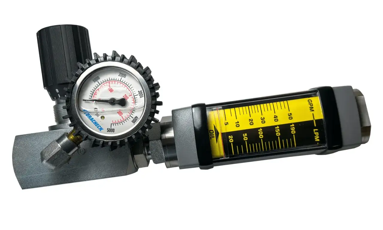
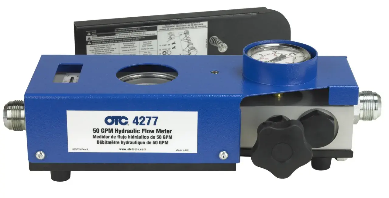
How to measure and read flow correctly
In the field, I never trust a flow number until I know where it was taken and under what load. A pump may look healthy on a test bench and still deliver disappointing performance in the machine because the circuit adds restrictions that the bench never had.
That is why a flow meter is most useful when it is paired with pressure and temperature readings. Flow without pressure tells me very little about usable work. Pressure without flow tells me very little about speed. Together, they show whether the system is healthy, throttled, leaking, or running outside its comfort zone.
| Unit | Where you will see it | Practical note |
|---|---|---|
| L/min | Most UK hydraulic equipment, valves, pumps, and test gear | The everyday unit for sizing and troubleshooting |
| m3/h | Larger process and water-related systems | 1 m3/h = 16.67 L/min |
| US gpm | Imported catalogues and North American documentation | 1 US gpm is about 3.785 L/min, so do not confuse it with a UK gallon |
Two practical details matter here. First, measure at operating temperature if you can, because cold oil can make a system look artificially poor. Second, check both the inlet and the outlet conditions of the pump. A pump restricted on the suction side may make noise, aerate the oil, and appear weak even when its output side is still intact. That leads straight into the real-world causes of lost flow.
What steals flow in real installations
Most poor-flow complaints are not caused by a single dramatic fault. They come from a stack of small losses that add up. In my experience, the most common culprits are predictable, which is good news because predictable problems are usually fixable.
- Undersized hoses or pipes. These create unnecessary pressure drop and can choke the circuit even when the pump is healthy.
- Dirty filters and strainers. As contamination builds, the pressure loss across the element rises and available flow falls.
- Over-throttled valves. A control valve can stabilise motion, but if it is doing too much restriction work, it burns energy as heat.
- Cold or overly viscous fluid. Thick oil resists movement, especially at start-up, and can make the machine feel slow until it warms.
- Cavitation or poor suction conditions. A noisy pump is often a clue that inlet flow is being starved.
- Internal leakage. Wear in pumps, valves, or cylinders can divert flow internally, so the circuit appears to have output on paper but not at the actuator.
Pneumatic systems have their own version of this problem, but the compressibility of air makes them even more sensitive to line length, leaks, and poor regulation. That is why a pneumatic axis that looks fine at low speed can become erratic when the cycle rate rises.
Once you know where the losses come from, the more useful question becomes how to choose components that avoid them in the first place.
Choosing pumps, valves and lines for stable flow
When I am comparing options, I look at the whole circuit, not just the pump. A bigger pump is not automatically a better system if the valves, hoses, and cooler cannot pass the flow cleanly. In many cases, better flow control comes from smarter component matching rather than brute force.
| Component choice | Best for | Main trade-off |
|---|---|---|
| Fixed-displacement pump | Simple, rugged circuits with steady demand | Excess flow must be managed elsewhere |
| Variable-displacement pump | Circuits that need efficiency and changing demand | Higher cost and more control complexity |
| Pressure-compensated flow control valve | Repeatable actuator speed as load changes | Can still waste energy if it throttles heavily |
| Larger line sizes | Lower pressure drop and cooler running | More space, cost, and fluid volume |
For precision motion, I usually prefer a valve or pump strategy that controls flow directly rather than trying to mask a poor layout with pressure. That is especially true in automation cells where repeatability matters more than raw force. If the machine has servo or proportional control, the quality of the flow signal becomes even more important, because small instability shows up as position error or cycle variation.
In practical terms, the best result often comes from three things working together: correct line sizing, clean supply conditions, and a control element that can hold flow steady under load. If one of those is missing, the system usually tells you by running hot, sounding rough, or drifting out of cycle time. The final step is turning that diagnostic logic into a habit on the shop floor.
When flow data starts telling the real story
The most useful flow number is the one you can compare against a baseline. Once I have that baseline, I can spot wear, restriction, and leakage before the machine fails outright. That is where fluid power starts to overlap with industrial automation and connected monitoring: a simple sensor trend can tell you more than a single alarm ever will.
If I had to reduce the whole subject to one working habit, it would be this: measure flow where it matters, compare it with pressure and temperature, and ask whether the circuit is delivering the motion you actually need. That approach is practical, fast, and far more reliable than guessing from component size alone.
For day-to-day engineering work, that means treating flow as a live performance metric rather than a catalogue figure. If the actuator reaches speed on time, the pressure stays within range, and the oil stays under control, the circuit is doing its job.