In fluid power, the difference between stable motion and wasted energy is often the valve choice. A linear control valve modulates flow by moving a closure member in a straight line, which makes it useful when you need predictable throttling, repeatable response, and fine control of actuator speed. I will break down how it works, where it fits in hydraulic and pneumatic circuits, how it compares with rotary designs, and what I would check before I put one into service.
What matters most before you choose one
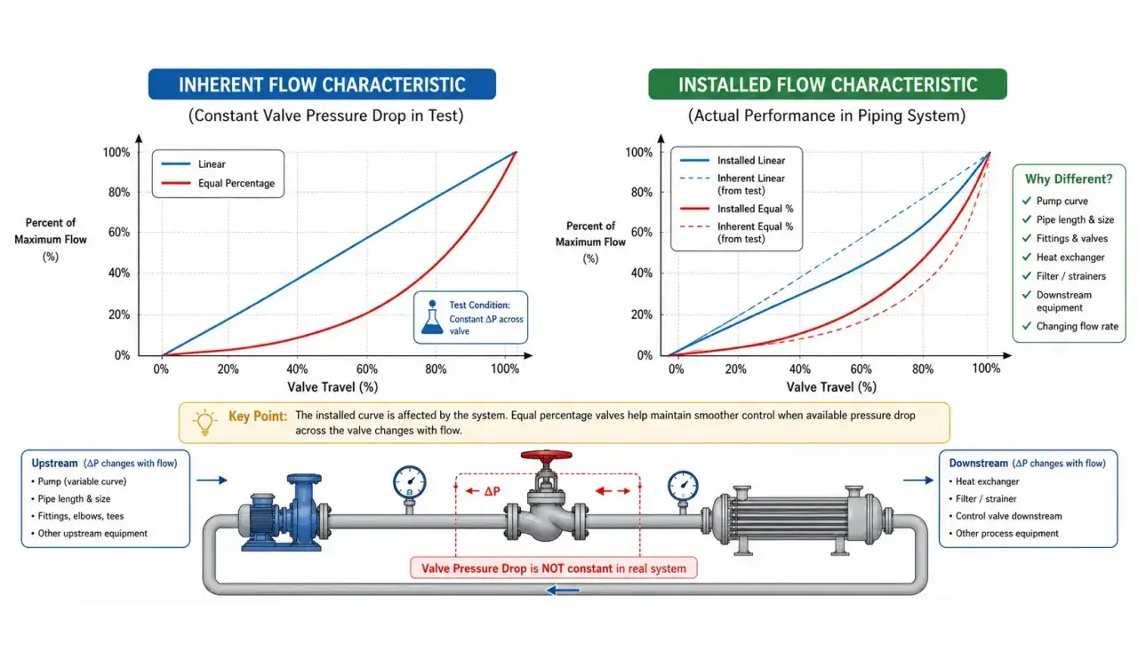
- It controls flow by straight-line motion, but that does not automatically mean the flow curve is mathematically linear.
- It is strongest where smooth throttling and repeatable control matter more than simple on/off duty.
- In hydraulic circuits, it directly affects actuator speed, pressure drop, and heat generation.
- In pneumatic circuits, it still works well, but compressibility makes the loop less rigid and more sensitive to tuning.
- Selection comes down to flow capacity, pressure rating, media cleanliness, response time, and fail-safe behaviour.
- Most bad results come from oversizing, contamination, or ignoring the control loop around the valve.
How straight-line motion regulates flow
The basic idea is simple: a stem, spool, plug, or similar element moves along one axis and changes the opening inside the valve body. That changing opening alters the pressure drop across the restriction, and the circuit turns that into a change in flow. Emerson groups control valves into sliding-stem and rotary families; the straight-line family is the one I reach for when I care about precise throttling and predictable movement.
The part that people often miss is that linear motion is not the same thing as a linear flow curve. A valve can move in a straight line while still having an equal-percentage or quick-opening characteristic. That is why trim shape matters so much. The trim is the internal geometry that actually meters the fluid, and it often decides whether the valve feels calm and controllable or abrupt and difficult to tune.
In practice, I also think about the actuator as part of the valve, not an afterthought. A good body with a weak actuator still gives poor control. A decent actuator with sloppy feedback gives the same problem in a different way. If the valve is part of a closed-loop system, the positioner or controller has to know where the element really is, not just where it was commanded to go. That leads directly into where these valves earn their place in real fluid power circuits.
Where it fits in hydraulic and pneumatic circuits
In hydraulics, these valves are used when I need to modulate cylinder or motor speed, hold a load more gracefully, or shape acceleration and deceleration instead of slamming an actuator from stop to stop. Traditional hydraulic architecture often splits the job into direction, speed, and pressure control. A proportional or servo-style linear valve can consolidate some of that control into one device, which simplifies the circuit but raises the bar on cleanliness and tuning.
Meter-in and meter-out control matter here. Meter-in means the valve restricts flow into the actuator; meter-out restricts flow leaving it. For overrunning loads, I usually find meter-out more stable because it gives the circuit something to push against, although it can raise backpressure and waste more energy as heat. That trade-off is normal, not a flaw in the valve itself.
In pneumatic systems, the same motion principle still applies, but compressed air behaves differently from oil. Air is more compressible, so the actuator response feels springier and less rigid. That can be fine for packaging equipment, pick-and-place stations, clamping, or small handling systems, but it is a poor match for applications that need very tight force control. In those cases, the valve can be technically correct and still be the wrong answer for the job.
Across UK plants, I most often see this type of valve in machine tools, presses, test rigs, automated handling lines, and process skids where a steady motion profile matters more than brute speed. The common thread is that the valve is not just opening and closing; it is shaping the motion of the machine. That naturally raises the question of whether a rotary design might do the same job more simply.
Linear vs rotary designs and when each makes sense
Emerson’s basic split between sliding-stem and rotary control valves is useful because it maps directly to how the valve behaves in service. Spirax Sarco makes a similar point from a practical angle: globe-style bodies are popular in throttling duties because the opening can be shaped into a specific flow characteristic. The right choice depends less on fashion and more on the shape of the duty cycle.
| Criterion | Straight-line design | Rotary design |
|---|---|---|
| Control quality | Usually very good for fine throttling and repeatable modulation | Often good, but best known for compactness and quick quarter-turn action |
| Footprint | Taller and more stroke-sensitive | More compact in many installations |
| Pressure behaviour | Can be excellent, but depends heavily on trim and sizing | Can offer strong flow capacity in a smaller package |
| Maintenance focus | Trim wear, packing, stem guides, actuator alignment | Seats, bearings, seals, and rotational backlash |
| Best fit | Precise control, smooth actuator motion, tighter throttling duties | Higher-capacity or compact applications where rotation is acceptable |
| Typical downside | Can be less compact and more sensitive to setup | May be less natural when the duty needs very fine linear modulation |
I do not treat this as a winner-takes-all comparison. If the circuit needs fine control at a narrow operating band, the straight-line design often wins. If space is tight, flow is high, and the duty is less sensitive, a rotary valve can be the cleaner answer. The real decision starts when you turn that theory into a specification.
What I would check before specifying one
When I review a valve for a real project, I start with the duty point, not the catalogue headline. In the UK, that usually means keeping the numbers in bar and litres per minute from the start so nobody is quietly converting between units and guessing. A valve that looks generous on paper can still be a poor fit if it spends all day near the end of its travel or if it creates too much pressure drop in normal operation.
- Flow capacity - Make sure the valve can handle the real operating range, not just the peak case.
- Pressure drop - Too much drop becomes heat in hydraulics and lost efficiency in any throttling circuit.
- Rangeability - This is the span between the smallest controllable flow and the largest useful flow; a wider range is easier to tune.
- Media cleanliness - Small clearances are unforgiving, so contamination control is not optional.
- Response time - If the valve is too slow, the controller will hunt; if it is too aggressive, the loop can become twitchy.
- Fail position - Decide whether the safe state is open, closed, or held, and make sure the actuator supports it.
- Feedback and diagnostics - Position feedback matters when the process needs repeatability, not just movement.
- Materials and seals - Fluid compatibility, temperature, and wear life all show up here sooner than people expect.
Two technical terms deserve quick definition. Deadband is the small command range that produces no visible movement. Stiction is the extra force needed to start motion after the valve has been sitting still. Both make a loop feel sticky or inconsistent, and both are easier to prevent than to tune out later. If the specification is still open, the next section is the one that saves most teams the most trouble.
The mistakes that turn good control into unstable control
The first mistake is oversizing. People often size for peak flow, then run the machine at a much lower normal flow. That leaves the valve working near the bottom of its stroke, where control gets coarse and the controller starts to chase tiny changes. I would rather see a valve sized for the real operating band with a little headroom than a giant body that spends its life half bored and half unstable.
The second mistake is treating contamination as a maintenance issue instead of a design issue. In a tight hydraulic loop, dirty oil will ruin precision long before it causes a dramatic failure. A bit of wear in the trim or spool can show up as drift, chatter, or slow response months before anybody notices a leak. If you only inspect the valve when something goes wrong, you are already behind.
The third mistake is assuming that the valve alone will cure a bad circuit. It will not. If the pump is poorly matched, the actuator is undersized, the relief settings are wrong, or the piping layout is noisy, the valve ends up compensating for somebody else’s error. That is where a good control valve gets blamed for a problem it did not create. In my experience, the cleanest results come when the valve, actuator, fluid quality, and controller are designed as one system.
The last common mistake is ignoring heat. Every throttling point creates a pressure drop, and in hydraulics that pressure drop becomes heat in the oil. If the circuit spends most of its life throttling heavily, efficiency suffers and temperature rises. That is the point where I start asking whether the architecture itself should change, not just the valve choice. From there, keeping the system healthy becomes much simpler.
Keeping it stable after commissioning
Once the valve is installed, the real work is keeping the motion repeatable. I would check the first few operating cycles carefully because bedding-in often changes packing friction, coupling alignment, or calibration. If the response seems different after the first hours or days, that does not automatically mean the valve is defective; it often means the system has settled into its real operating condition.
- Verify that the actuator is receiving the right supply pressure or electrical command.
- Keep the fluid or air supply clean and dry enough for the valve’s internal clearances.
- Watch for slow response, hunting, chatter, or drift, because those are early warning signs.
- Inspect seals, guides, couplings, and packing before wear becomes visible at the machine level.
- Trend travel, pressure differential, and response time instead of waiting for a hard fault.
Modern diagnostics make this easier, but they do not replace discipline. The best-performing installations are still the ones where the maintenance team knows what normal looks like and reacts before the valve starts to fight the controller. That brings me to the last rule I trust when a circuit is still being refined.
The specification rule I trust when the circuit is still evolving
If I had to keep only one rule, it would be this: size the valve around the real operating point, not the nameplate maximum. That single decision has more impact on controllability than most people expect. A valve that is technically capable of the flow you need can still be a bad fit if it lives at the wrong part of its curve or if the actuator cannot position it consistently.
In 2026, the easiest win is still the boring one. Match the valve to the duty, keep the fluid clean, use enough feedback to make the control loop honest, and leave room for the system to breathe. If the application needs precise, repeatable motion in a hydraulic or pneumatic circuit, a straight-line design is often the right starting point. If the application is more about compactness or simple rotation, I would compare alternatives before committing. Either way, the valve is only one part of the answer, and the best results come when the whole circuit is designed to work with it, not around it.