To answer what is a physical layer, start with the part of networking that turns data into real signals on a real medium. In this article I explain what Layer 1 does, how it differs from the layers above it, which hardware and media it depends on, and why it matters so much in industrial and IoT environments. If you want a practical explanation rather than a textbook gloss, this is the right place to begin.
The physical layer is where bits become signals
- Layer 1 converts raw bits into electrical, optical, or radio signals that can move across a medium.
- It covers timing, encoding, transmission mode, connectors, cabling, and distance limits.
- It does not handle IP addresses, routing decisions, or frames.
- Copper is simple and affordable, fibre is stronger over distance and in noisy spaces, and wireless adds mobility.
- Many “network” faults are really Layer 1 faults in disguise.
What the physical layer actually does
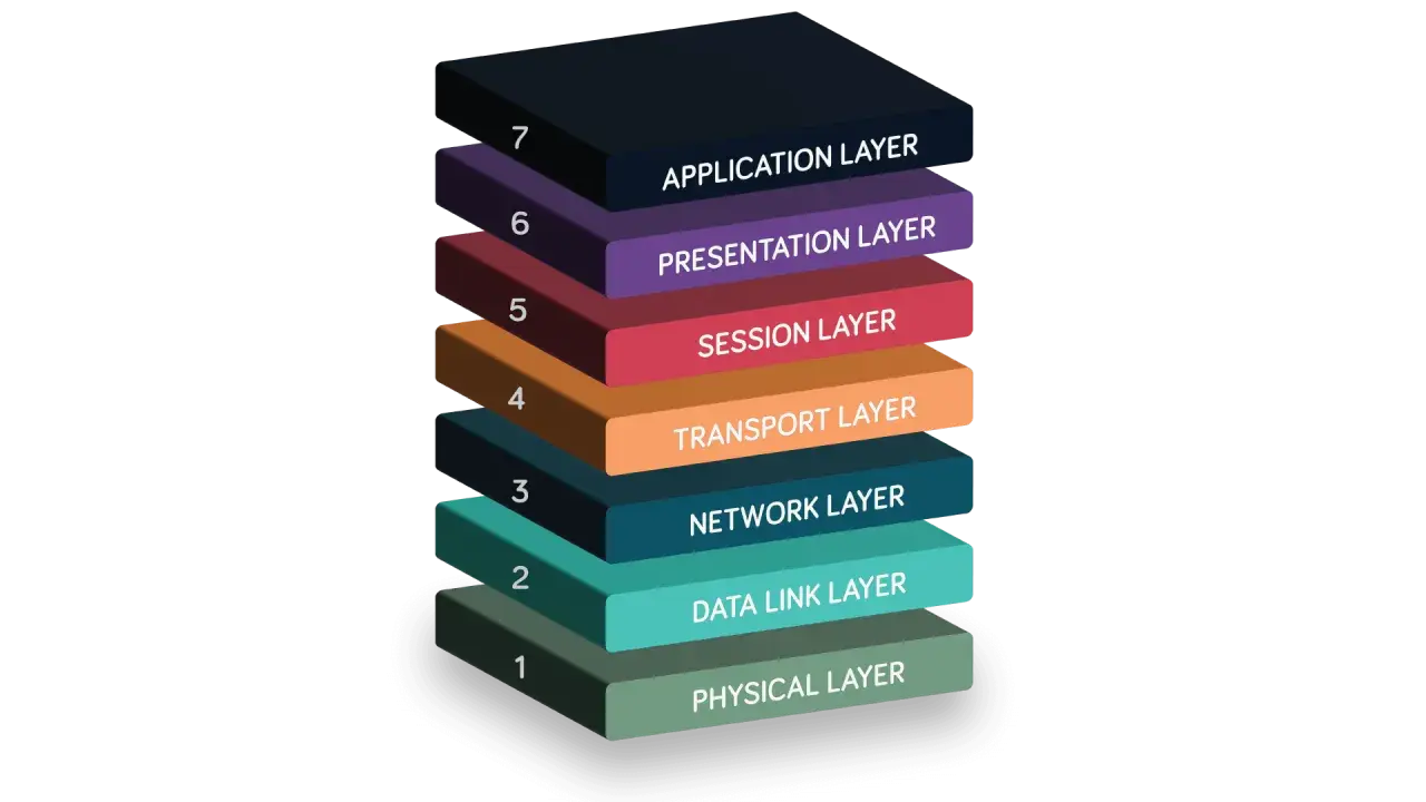
The physical layer is the bottom of the OSI model, but it is not the least important part of the stack. Its job is to move a stream of bits from one point to another by turning those bits into something the medium can carry: voltage changes on copper, light pulses in fibre, or radio waves in wireless systems. That sounds simple until you remember that the sender and receiver also need to agree on timing, signalling, and how a 1 and 0 are represented in the first place.
I usually describe Layer 1 as the point where networking stops being abstract. It deals with bit rate, bit synchronisation, encoding or modulation, and transmission mode such as simplex, half duplex, or full duplex. It also shapes the physical topology, which is just the way devices are connected together at the cabling or radio level. A star-shaped Ethernet network and a mesh wireless network may behave very differently above the wire, but both depend on Layer 1 being stable underneath.
- Bit rate defines how much data can be sent per second.
- Synchronisation keeps sender and receiver aligned at the bit level.
- Encoding defines how ones and zeros are represented physically.
- Transmission mode controls whether data flows one way or both ways.
- Topology describes the physical layout of the link or network.
Once that basic job is clear, the next step is to look at the actual media and hardware that carry the signal.
The hardware and media behind the signal
Layer 1 is not just “the cable”. It includes the interface on the device, the transceiver, the connector, the line discipline, and the medium itself. In practice, that means network interface cards, ports, SFP modules, antennas, repeaters, patch leads, and the physical path between devices. If any one of those pieces is weak, the whole link can become unstable.
The choice of medium matters because each option has a different trade-off profile. Copper is easy to install and cheap to terminate, but it is more vulnerable to interference. Fibre is excellent for long runs and electrically noisy environments, but it costs more and demands cleaner handling. Wireless is ideal when mobility or retrofitting matters, but it gives up some predictability to congestion, interference, and placement.
| Medium | How it carries data | Strengths | Trade-offs | Best fit |
|---|---|---|---|---|
| Copper twisted pair | Electrical voltage changes | Low cost, easy to deploy, often supports power delivery | Susceptible to EMI, crosstalk, and distance limits | Offices, control cabinets, short industrial links |
| Fibre optic | Light pulses through glass or plastic fibre | Long distance, high bandwidth potential, strong immunity to noise | Higher installation cost, more careful handling, optics required | Backbones, harsh electrical environments, long runs |
| Wireless | Radio signals through the air | Mobility, fast deployment, no physical cabling needed | Interference, congestion, and placement sensitivity | Mobile devices, sensors, hard-to-wire areas |
There is one practical number I keep in mind because it saves people from bad assumptions: standard copper Ethernet runs are typically limited to about 100 metres end to end. If you need more distance, or if the environment is electrically harsh, fibre is often the cleaner answer. That media choice becomes even more important once you compare Layer 1 with the layer above it.
How it differs from the data link layer and TCP/IP
People often blur Layer 1 and Layer 2 together because both are part of the lower network stack, but they do different work. The physical layer moves signals. The data link layer wraps those signals into frames, handles local addressing, and manages how devices share the medium. In TCP/IP, those responsibilities are often grouped into the network access layer, which is why the boundary can feel fuzzy at first.
The easiest way to separate them is to ask what kind of problem you are solving. If the issue is “can the signal travel cleanly from one device to another?”, that is Layer 1. If the issue is “which device gets the frame, and how do we make local delivery reliable?”, that is Layer 2. I find that distinction useful because it prevents people from chasing routing, IP, or application settings when the real fault is a bad cable or transceiver.
| Layer 1 | Layer 2 | TCP/IP network access layer |
|---|---|---|
| Moves raw bits as signals | Creates frames and local delivery rules | Combines the practical work of Layers 1 and 2 |
| Focuses on medium, timing, and signalling | Focuses on MAC addresses, framing, and local access | Focuses on hardware and software needed to reach the medium |
| Common failures: attenuation, EMI, damaged cabling | Common failures: framing errors, addressing, switching issues | Often appears as a mix of both kinds of faults |
| Does not decide where packets go | Decides how frames move on the local network | Provides the link between the host and the physical network |
That boundary matters because Layer 1 failures tend to look messy in the real world, and the next section shows why they are so often misdiagnosed.
Where Layer 1 breaks down in real networks
When a network feels “randomly slow” or a device keeps dropping off the link, I usually start at the physical layer before I touch anything else. Layer 1 problems do not always announce themselves clearly. They often show up as a link light that flickers, throughput that collapses under load, or equipment that works only until someone moves a cable or powers on a noisy machine nearby.
The common causes are predictable once you know what to look for. Attenuation is signal loss over distance. Crosstalk is interference between neighbouring conductors. EMI, or electromagnetic interference, comes from motors, drives, welders, relays, and other electrically noisy equipment. In fibre systems, dirty connectors and damaged ends can be just as disruptive as interference in copper. In wireless, poor antenna placement or obstruction can be enough to make a link unreliable.
| Symptom | Likely Layer 1 cause | First thing I would check |
|---|---|---|
| Link drops in and out | Loose connector, damaged cable, bad termination | Patch lead, port seating, physical strain on the cable |
| Works at a lower speed but not full speed | Marginal cable quality or termination | Cable category, crimps, transceiver match |
| Errors appear near heavy machinery | EMI or poor shielding | Cable routing, grounding, shield integrity |
| Fibre link is unstable after cleaning was ignored | Dirty or damaged fibre ends | Connector inspection and proper cleaning |
| Wireless link is inconsistent across the site | Poor placement, obstruction, or interference | Antenna location, line of sight, channel overlap |
There is a pattern here: the problem is often not “the network” in a broad sense, but the path that carries the signal. That becomes much more obvious in industrial and IoT installations, where the environment is far less forgiving.
Why it matters in industrial automation and IoT
Industrial networks put Layer 1 under pressure in ways office networks usually do not. Cables run near motors, drives, and power lines. Devices vibrate. Cabinets heat up. Sensors are installed in places that are difficult to access. On top of that, many plants need links that are predictable, not just fast. A link that looks fine on paper can still fail in production if the medium, shielding, grounding, or connector choice is wrong.
This is where physical design becomes a practical engineering decision rather than a theory exercise. In a factory, I would often prefer fibre for long or noisy runs, especially where electrical isolation helps. For shorter copper runs, I would still pay attention to cable quality, shielding, bend radius, and how the cable is routed past noisy equipment. In IoT projects, the trade-off is different: wireless can make deployment far easier, but only if the site layout and interference pattern support it. The best answer is rarely “use the newest technology”; it is “use the medium that fits the environment”.
- Shielding matters when electrical noise is part of daily operations.
- Grounding matters because poor grounding can make shielding far less effective.
- Connector choice matters when vibration, dust, or movement are normal conditions.
- Distance matters because signal quality usually degrades before the software stack shows obvious errors.
- Power delivery matters when devices use Power over Ethernet or similar arrangements.
Once you think in those terms, Layer 1 stops being background detail and starts becoming the foundation of uptime, which leads naturally to the decisions that make it dependable in the first place.
The decisions that make Layer 1 dependable
The most reliable Layer 1 designs are usually the least dramatic. They use the right medium for the environment, keep runs within sensible limits, and avoid forcing a link to do a job it was never meant to do. That sounds obvious, but in the field it is exactly where expensive mistakes happen. People overspecify speed, underspecify cabling, or underestimate how much noise and motion a site introduces.
- Choose copper when the run is short, the environment is quiet, and cost matters most.
- Choose fibre when you need distance, electrical isolation, or better immunity to EMI.
- Choose wireless when mobility, retrofit constraints, or temporary deployment make cabling impractical.
- Keep copper channels within standard length limits and avoid sloppy patching.
- Inspect and clean fibre connectors before assuming a software fault.
- Route signal cables away from power equipment, variable-frequency drives, and other noisy sources.
- Verify grounding, shielding, and bend radius before chasing higher-layer issues.