The suction side of pump systems is where flow quality is decided before the liquid ever reaches the impeller. If that inlet path is short, smooth and properly primed, the pump runs quietly and predictably; if it is restrictive, aerated or poorly arranged, the whole system becomes harder to control. I’m going to break down what the inlet does, why cavitation starts there, and how I would design and check the line so the pump has a fair chance of doing its job.
The inlet side decides whether the pump starts cleanly or fights itself
- Keep the suction line short and simple. Every extra elbow, valve or constriction steals pressure before the liquid reaches the pump.
- Control inlet velocity. In many water services, I would try to stay around 1.8-2.0 m/s or lower on the suction side.
- Watch NPSH, not just pressure. The inlet needs enough head above vapour pressure to avoid cavitation.
- Air leaks are as damaging as hard restrictions. A tiny leak on the inlet can pull in air and create noise, vibration and unstable flow.
- Good commissioning matters. Filling, venting and baseline checks often decide whether a pump stays healthy or becomes a maintenance case.
What the inlet side actually does
I like to think of the pump inlet as the point where the whole system is either handed a clean supply of liquid or a problem it has to fight through. The pump does not magically drag fluid in like a vacuum cleaner; it lowers pressure at the inlet and relies on the rest of the system to feed it without starving the impeller or inlet chamber.
For a centrifugal pump, the liquid enters the eye of the impeller. For a positive displacement pump, the inlet has to fill the pumping chambers properly on every cycle. The principle is the same in both cases: the inlet must be able to deliver enough liquid, at the right pressure, without excessive turbulence or air.
This is why the difference between a flooded suction and a suction-lift arrangement matters so much. A flooded suction gives the pump a head start because the liquid level sits above the pump centre line. A suction-lift system can work, but it is less forgiving and makes priming, sealing and air control much more important. Once you see the inlet as part of the machine rather than separate pipework, the rest of the design logic becomes easier to follow.That leads directly to the real failure modes, because most inlet problems become visible only after the pump starts running.
Why poor inlet conditions damage performance
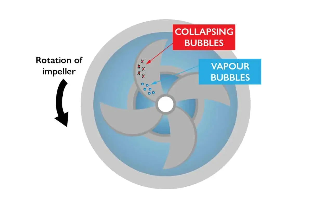
The main risk on the inlet side is cavitation. That happens when the pressure falls close to, or below, the vapour pressure of the liquid, so vapour bubbles form and then collapse inside the pump. The collapse is violent enough to cause noise, vibration, pitting, reduced head and shortened seal and bearing life.
NPSH is the term that keeps this discussion honest. It is a head value, not just a pressure reading, and it compares the pressure energy available at the inlet with the pressure the pump needs to avoid flashing the liquid. If the available margin is too small, the pump may still run, but it is running in a stressed state that usually shows up later as unreliable operation.
In practice, cavitation is not the only problem. I also watch for:
- Air ingress, especially through loose joints, poor gasket faces or worn seals on the inlet side.
- Turbulence, often caused by elbows, tees, valves or branches too close to the pump nozzle.
- Vortexing, which can pull air into a tank outlet or sump and give the pump an aerated feed.
- Excess temperature, because warmer liquid has a higher vapour pressure and a smaller operating margin.
- Solids loading, which increases erosion if the suction velocity is too high.
Grundfos points out that reducing friction loss in the suction pipe is one of the practical ways to avoid cavitation, and that is exactly the right way to think about it: every bit of loss upstream makes the inlet condition worse. Once the failure modes are clear, the next step is to shape the suction line so those losses never get a chance to build up.
How I would design the suction line
This is the part where small design choices pay back for years. I usually start with three rules: keep the line short, keep the velocity low, and keep the flow smooth as it reaches the pump. Michael Smith Engineers recommends keeping suction velocities below about 2 m/s in many services, and I think that is a sensible working target for a lot of industrial water applications.
Where layout allows, I also prefer the suction pipe to be one nominal size larger than the pump inlet. That is not a universal law, but it is a practical way to reduce friction loss and make the inlet less sensitive to small disturbances. I would rather spend a little more on pipe than spend years compensating for a marginal inlet.
| Design choice | What it does | Why I care |
|---|---|---|
| Short straight run before the pump | Helps the flow arrive more evenly | Reduces swirl, uneven velocity and local pressure loss |
| Eccentric reducer with the flat side on top | Prevents an air pocket forming at the high point | Stops vapour from being trapped at the inlet |
| Few fittings near the nozzle | Keeps turbulence away from the pump | Improves inlet stability and lowers cavitation risk |
| Low suction velocity | Reduces friction loss | Preserves NPSH available at the pump |
| Proper venting and priming | Removes trapped air before start-up | Prevents dry running and unstable discharge |
KSB makes the same point in a slightly different way: elbows, valves and branches upstream of the pump can disturb inlet flow enough to affect operating behaviour. I would go one step further and say that a badly arranged suction line can undo the benefit of a well-chosen pump. The pump may be right; the inlet arrangement may not be.
There is one more detail I would not ignore: if a strainer is needed, it should be sized and maintained so it does not become the dominant source of loss. A dirty strainer on the inlet side is often just a cavitation problem waiting for the right operating point.
Good design helps, but commissioning is where many of these decisions are either confirmed or wasted.
What I would verify during installation and start-up
I like commissioning to feel boring. If it is noisy, rushed or unclear, the suction side usually pays for it later. Before the pump is handed over, I would verify the line mechanically, hydraulically and operationally.
- Check for air leaks on every suction-side joint, gasket and threaded connection.
- Confirm the pump is fully primed and, where needed, vented before start-up.
- Support the pipe properly so the pump casing is not carrying the weight of the line.
- Inspect the strainer or inlet screen and clean it before the first run.
- Verify rotation direction on the motor and confirm that valves are set as intended.
- Record baseline values for suction pressure, discharge pressure, current draw, noise and vibration.
In suction-lift systems, I would be even stricter. If the pump has to lift the liquid, any loss of prime or small air leak becomes more serious, and some installations need a non-return valve in the inlet line to help hold prime. If the system is not properly filled and vented, the first few minutes of operation can tell you a lot about the future maintenance burden.
Once the pump is in service, the same inlet condition can be monitored rather than guessed, which is where modern automation starts to add real value.
How it fits into fluid power and smart monitoring
In fluid power systems, the inlet side matters just as much as it does in process pumping. A hydraulic power unit that is starved at the inlet will not respond cleanly, and the consequences can show up as pressure ripple, sluggish actuators, heat build-up or a pump that sounds healthy until it suddenly does not. I would treat the inlet as part of the control loop, not just part of the pipework.
That is where connected monitoring changes the conversation. A simple pressure transmitter on the suction line, paired with vibration and temperature data, can reveal a degrading condition long before a seal fails. In a smart manufacturing environment, I would look for trends rather than alarms alone: a slow drop in suction pressure, a rising vibration signature, or a change in motor load under the same duty point often tells the story before the operator hears anything unusual.
| Pump type | What the inlet needs most | What usually goes wrong first |
|---|---|---|
| Centrifugal | Stable, non-aerated flow with enough NPSH margin | Cavitation, head loss and noisy operation |
| Positive displacement | Full prime and a steady feed without starvation | Pulsation, heat rise, seal wear and overload risk |
This distinction matters because the same suction problem does not always show up in the same way. A centrifugal pump may become noisy and lose performance; a positive displacement pump may keep building pressure while quietly heating the fluid and stressing the drive. Either way, the inlet has become the weak link. Once that is clear, the practical question is how to keep a plant operator or maintenance engineer one step ahead of it.
The plant-floor checks I would keep close
If I had to reduce the whole topic to a short working list, it would be this: make the inlet easy for the liquid to enter. That means low velocity, few disturbances, no trapped air, proper priming and enough NPSH margin for the actual duty point, not the idealised one on paper.
- Keep the suction run short and direct.
- Use larger pipe where the hydraulics allow it.
- Place elbows, valves and branches away from the pump nozzle.
- Use the right reducer orientation to avoid trapping air.
- Watch inlet pressure, temperature and vibration trends, not just trips.
- Recheck the line after any maintenance that opens the suction side.
The suction side of pump equipment is not a place to save effort, space or a small amount of pipe cost. It is the part of the system that decides whether the pump will operate smoothly for years or spend those years fighting cavitation, air ingress and unstable inlet conditions. If you design and monitor that section properly, the rest of the fluid power system becomes much easier to live with.