
A hydraulic cylinder's stroke is easy to misread if you only look at the overall body length. This guide shows how to measure hydraulic cylinder stroke without confusing it with retracted length, installed length or the travel of the machine it powers. I also cover the practical traps that matter in fluid power work: where to take the reference points, what changes on telescopic units, and when a sensor is a better tool than a tape measure.
Key points that save time before you measure
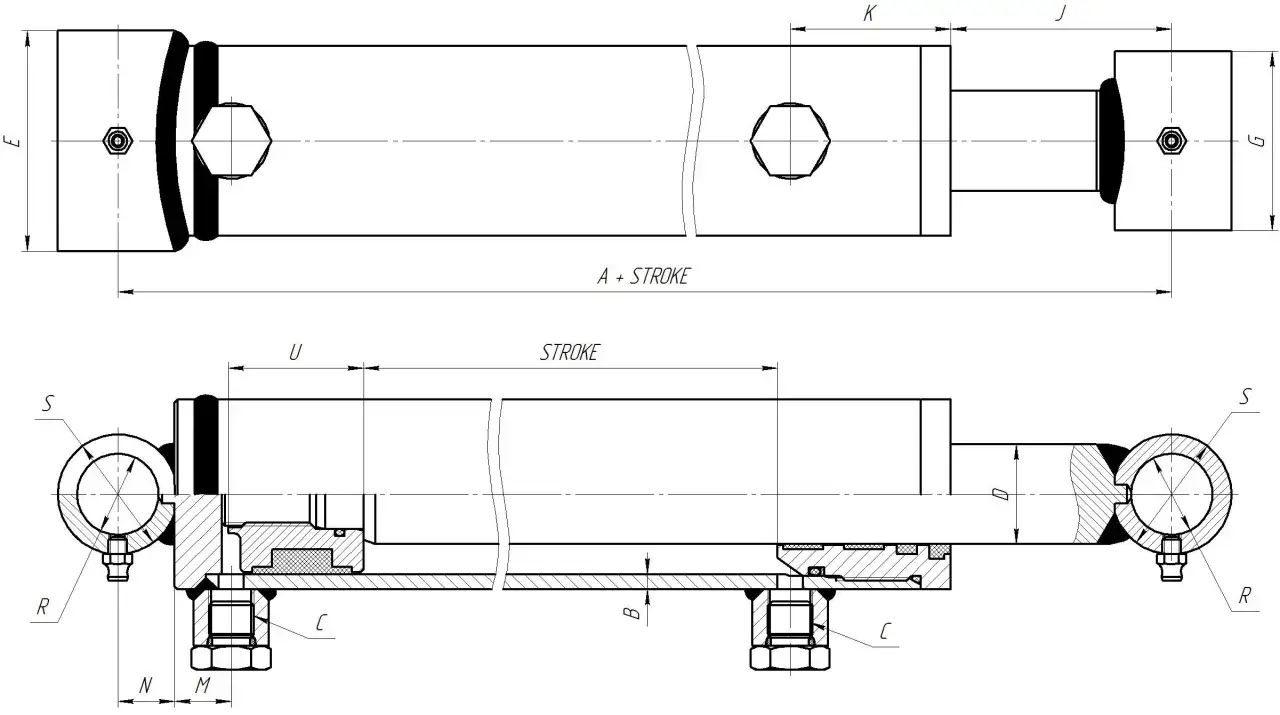
- Stroke is the distance the rod travels from fully retracted to fully extended.
- Measure between the same reference points at both ends, then subtract.
- For installed cylinders, use a fixed machine datum, not the load travel through a linkage.
- Telescopic cylinders need the sum of the stage strokes, not the collapsed body length.
- If the cylinder is part of automation, a position sensor can give a cleaner reading than manual checking.
What stroke actually means in a hydraulic cylinder
The stroke is the usable straight-line travel of the piston rod between its fully retracted and fully extended positions. In practice, I treat it as a movement number, not a body-size number.
| Term | What it means | Why it matters |
|---|---|---|
| Stroke | The distance the rod travels from one end of travel to the other. | This is the number that affects reach, cycle time and fit. |
| Retracted length | The cylinder length when the rod is pulled fully in. | This helps with installation space, but it is not the stroke. |
| Installed length | The space the cylinder occupies once mounted in the machine. | Mounts, clevises and brackets change this, so it can mislead you. |
Stroke = extended reference length - retracted reference length. If the centre-to-centre length is 420 mm when retracted and 720 mm when extended, the stroke is 300 mm. I keep the calculation in millimetres until the end, because that is usually where the fit-up tolerances are decided.
One common mistake is to use machine output travel as a substitute for cylinder stroke. That only works on direct-acting layouts. Once a lever, bell crank, scissor link or wedge enters the picture, the output movement and the rod travel are no longer the same thing. Once you separate stroke from overall length, the actual measurement becomes straightforward.
The simplest way to measure a cylinder on the bench
If the cylinder is loose and safe to handle, this is the cleanest method because you control both end positions. I usually use a steel rule for short units, a tape measure for longer ones, and a dial indicator when I need better than 1 mm repeatability.
- Depressurise the cylinder fully and make sure it is not carrying a suspended load.
- Clean the rod and choose two reference points that belong to the same moving path.
- Fully retract the cylinder to its true mechanical stop or documented retract position.
- Fully extend it to its true mechanical stop or documented extend position.
- Measure the same datum at both ends, then subtract the retracted reading from the extended reading.
For pin-mounted cylinders, I measure centre to centre between the pin bores. For threaded rod ends or clevises, I use the drawing's reference face and a marked point on the rod end rather than the edge of a bracket, because bracket thickness is an easy place to introduce a 1 to 2 mm error. If the cylinder is old, worn or modified, I check the actual metalwork twice before trusting the nominal size.
Tip Align the tape or rule with the cylinder axis. If you measure at an angle, the error may be small on a short cylinder, but it grows quickly on a long one. If the cylinder is still bolted into a machine, the same principle applies, but the reference points change.
How I measure stroke when the cylinder is still on the machine
When the cylinder is already installed, I work from the machine's fixed structure, not from the moving load. That sounds obvious, but it is where bad numbers usually start.
- Lock out the system and support the load mechanically before touching any measurement point.
- Mark one fixed datum on the frame and one moving datum on the rod, clevis or attachment point.
- Cycle the cylinder to the retracted position and record the distance.
- Cycle it to the extended position and record the distance again.
- Subtract the two readings to get the stroke.
- Repeat the check if there is backlash, float or visible creep as pressure bleeds off.
If the cylinder works through a linkage, the number at the load end is not the stroke. I would treat that as a different measurement altogether, because geometry can magnify or reduce motion by a surprising amount. In a direct-acting press, a 300 mm stroke remains a 300 mm stroke; in a scissor lift, the load may move much farther than the rod itself.
If I cannot reach both end positions safely, I do not guess. I go back to the drawing, the nameplate or the supplier's data, because a partial movement can hide lost travel in the mounting geometry. That is especially true on compact machines where the cylinder disappears into the structure and only part of the rod is visible. Special cylinder designs, especially telescopic units, need a different approach.
Special cases that change the calculation
Not every cylinder behaves like a single-stage rod cylinder, and that is where people often get caught.
| Type | What changes | How I check it |
|---|---|---|
| Single-stage rod cylinder | Stroke is a simple straight-line travel. | Measure between the same reference points at both ends. |
| Telescopic cylinder | Several nested stages extend one after another. | Use the OEM stroke value or add the stage strokes together. |
| Long-stroke cylinder with a stop tube | The stop tube affects the installation envelope and support, not the basic travel label. | Trust the net stroke figure, not the extra internal hardware. |
| Sensor-equipped cylinder | Position is available as a live signal. | Zero at retract and confirm the full-scale reading before trusting it. |
A three-stage telescopic unit, for example, might contribute 120 mm on the first stage, 180 mm on the second and 250 mm on the third. The total stroke is then 550 mm, even though the collapsed package is much shorter than a conventional cylinder with the same reach. That compact package is the whole point of telescopic design, but it also means the collapsed length tells you very little on its own.
Long-stroke designs also deserve care when the cylinder is mounted horizontally. Extra internal support or a stop tube may be needed to control bearing load at full extension. I never treat those features as part of the stroke itself; they affect durability and installation space, not the travel number I am trying to verify. For automated systems, a sensor often tells the truth better than a tape measure.
When a position sensor is the better answer
In automation projects, I often prefer a position sensor once the same measurement has to be repeated every shift or sent into a PLC. A magnetostrictive transducer, for example, is a linear sensor that reads rod position continuously along the stroke, which is useful when manual access is awkward or the cylinder is hidden inside a machine frame.
- Use a sensor when you need repeatability, logging or alarm limits.
- Use it when the cylinder is internal, guarded or difficult to reach safely.
- Use it when wear, drift or load variation makes visual checking unreliable.
- Zero the sensor at the fully retracted position and confirm the full-scale value before trusting the reading.
If the sensor value and the physical rod movement do not agree, I treat that as a calibration issue until proven otherwise. A good sensor does not remove the need for a sanity check; it just gives you a better baseline than eyeballing a moving rod.
Even a correct reading can be ruined by a handful of avoidable errors.
The mistakes that give the wrong number
The wrong stroke reading usually comes from a simple mix-up, not a bad tape measure.
- Measuring the barrel or body length instead of rod travel.
- Using machine output travel from a linkage as a proxy for cylinder stroke.
- Forgetting rod-end adapters, clevis pins or bracket thickness when choosing reference points.
- Measuring a cylinder that is still loaded, pressurised or creeping off position.
- Assuming a telescopic cylinder can be judged from its collapsed length alone.
- Rounding a critical fit to the nearest 25 mm when the machine needs a tighter envelope.
Rule of thumb If the cylinder cannot reach both end positions freely and safely, the number is provisional, not final. I also avoid trusting a reading if the rod is bent, the bearings are worn or the machine is side-loaded, because each of those can distort the travel you think you are seeing.
Before I close a job, I always record a short set of dimensions so the number can be trusted later.
The few dimensions I always record before I sign off the stroke
Before I call a measurement finished, I write down more than one number. That takes a minute, but it saves a lot of arguments later when somebody tries to order a replacement or tune the control logic.
- Retracted length between the chosen reference points.
- Extended length between the same reference points.
- Calculated stroke in millimetres.
- Mounting style and end fittings.
- Rod diameter and any visible rod extension or stop tube.
- Whether the cylinder is direct-acting, telescopic or sensor-equipped.
Once those values are captured, the stroke stops being a guess and becomes a number you can actually use for selection, commissioning or fault finding. In fluid power work, that is usually the difference between a cylinder that fits first time and one that gets measured twice.