The essentials at a glance
- An isolation transformer transfers AC power through magnetic coupling, not a direct electrical connection.
- Its main job is to create galvanic isolation; many units are 1:1, but not all.
- It can reduce certain noise and fault pathways, but it is not a universal shock-proofing device.
- In UK systems, the secondary may be left floating or intentionally earthed, depending on the design objective.
- Selection usually comes down to voltage, VA rating, secondary earthing, enclosure, and standards compliance.
How it creates separation without stopping power
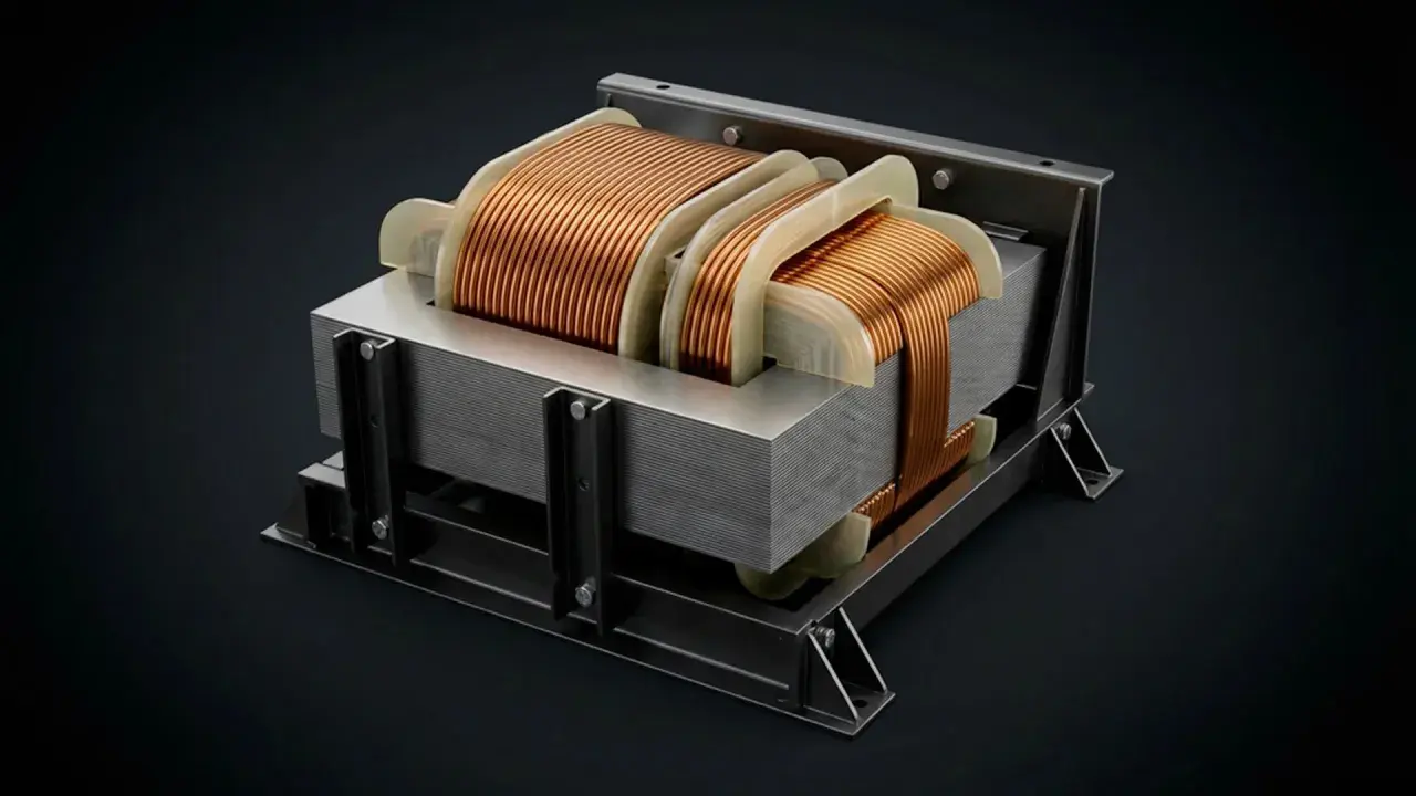
At its core, the device uses two windings on the same magnetic core: a primary winding connected to the source and a secondary winding connected to the load. Energy crosses the core by induction, so there is no direct conductive connection between input and output. That is why engineers call the result galvanic isolation.Many people assume the word "isolation" means the output is dead safe. It does not. A 1:1 unit may pass the same voltage through, and a step-down unit may still deliver a hazardous voltage. What changes is the relationship between the load and the supply, not the physics of electricity itself.
Many isolation transformers are built as 1:1 devices, but the same separation can also be used while stepping the voltage up or down. In other words, isolation is about the winding relationship, not about any single voltage ratio.
Primary, secondary, and the magnetic core
The primary creates a changing magnetic field, the secondary picks that field up, and the core keeps the coupling efficient. Some industrial transformers also include a Faraday screen between the windings. That screen is tied to earth and helps block capacitive noise, which is useful when drives, relays, or switch-mode supplies are polluting the panel.
Read Also: LED EMI Filter - Stop Noise & RCD Trips in UK Systems
Why the output can still look "live"
Even with isolation, the secondary can sit at some potential relative to earth because of leakage and capacitance. That is why a floating output can behave differently from a conventional mains circuit, especially during testing. The output is separate, but it is not magically harmless.
Once that split is clear, the next question is what the device actually protects against in the field.
What it protects against and what it does not
I usually separate the benefits into two buckets: what improves, and what simply changes form.
| Issue | What an isolation transformer usually does | What it does not do |
|---|---|---|
| Galvanic path from supply to load | Removes the direct conductive link | Does not remove all voltage risk on the secondary |
| Earth loops and common-mode noise | Often reduces them, especially with a screen | Does not replace filtering or good cable routing |
| Shock risk | Can reduce risk in the right earthing scheme | Does not make live work safe |
| Fault behaviour | Changes how earth faults appear | Does not guarantee automatic disconnection on its own |
| Surges and harmonics | May soften some coupling effects | Does not act as a full surge protector |
The line I never blur is this: it is not an RCD. A residual current device detects imbalance; the transformer changes the circuit topology. That difference matters when someone assumes the output is floating, so the fault current will simply "go nowhere". It may go nowhere useful, which is not the same thing as safe.
That is also why earth loop testing can look odd on a floating secondary: the circuit may have no deliberate return path until you define one. In UK practice, the secondary might be left floating, or one pole might be earthed on purpose, and those two options behave very differently during a fault.
Once you know the limits, the real question becomes where this device earns its keep on a plant floor or in a control panel.
Where it makes sense in UK electrical systems
On a 230V, 50Hz UK supply, I would not reach for an isolation transformer simply because the mains voltage is awkward. I would reach for it when the installation needs a different relationship between the load and earth, or when noise and service access matter more than a plain voltage change. On a modern line with PLCs, HMIs, drives, and edge devices, that can matter as much as the nominal voltage.
- Control panels and PLC test rigs - useful when you want a separated supply for bench testing, commissioning, or fault-finding without dragging the whole panel reference with you.
- Noise-sensitive instrumentation - helpful when analogue inputs, sensors, or measurement gear are being upset by common-mode noise from drives and contactors.
- Construction-site 110V centre-tapped-earthed systems - a common UK example built around a safety isolating transformer; each conductor sits at about 55V to earth to reduce touch voltage.
- Legacy or awkward equipment - older machines, oddball imported gear, and service benches sometimes behave better when the supply is electrically separated from the rest of the installation.
For industrial automation, I see the clearest value in maintenance and commissioning. A separated supply can make it easier to troubleshoot a board, a sensor loop, or a small auxiliary circuit without accidentally creating a second earth path through test gear. That said, I would not use isolation as a substitute for proper segregation, shielded cabling, or a sensible earthing strategy.
That leads naturally to the next distinction, because the transformer family names are often used as if they mean the same thing.
How it differs from an autotransformer and a safety isolating transformer
This is where terminology gets sloppy. People say "isolation transformer" when they really mean a transformer with extra safety insulation, or they say "transformer" when they actually want only a voltage change. The difference affects cost, size, wiring, and compliance.
| Device | Galvanic isolation | Typical strength | Main trade-off |
|---|---|---|---|
| Isolation transformer | Yes | Separates primary and secondary while still transferring AC power | Heavier and more expensive than a shared-winding design |
| Autotransformer | No | Compact voltage conversion with a shared winding | Cheaper and smaller, but no separation between input and output |
| Safety isolating transformer | Yes, with tighter construction requirements | Used where extra protection against electric shock is the design goal | Often less flexible, because the protection function drives the specification |
In the UK, the BS EN 61558 family is the usual reference point for the safety side of transformer selection, especially where the output is intended to support separated or extra-low-voltage arrangements. I would be careful here: not every isolation transformer is automatically the right answer for a safety-critical circuit, and not every safety transformer is ideal for noise control.
If the brief is simply "make the voltage different", an autotransformer can be the efficient answer. If the brief is "keep the circuits apart", the shared winding is a deal-breaker.
Once the type is fixed, the practical work starts: rating, earthing, enclosure, and protection.
How I would specify one for a real installation
When I specify one, I start with the load and the fault behaviour, not the catalogue page. A neat-looking part number is useless if the secondary is misreferenced, the transformer is undersized, or the protective device trips every time you energise the panel.
- Define the job - decide whether you need separation, noise reduction, voltage conversion, or a mix of all three.
- Match the electrical basics - confirm primary voltage, secondary voltage, frequency, phase, and whether the load is continuous or intermittent.
- Size in VA, not wishful watts - add 20-30% headroom for a steady load, and more if the load has inrush, harmonics, or a poor power factor.
- Choose the secondary arrangement - floating, centre-tapped, or intentionally earthed. This one decision changes how the circuit behaves during a fault.
- Check thermal and mechanical details - enclosure type, IP rating, mounting method, ambient temperature, insulation class, and ventilation all affect real-world life expectancy.
- Coordinate protection - the primary fuse or MCB must tolerate transformer inrush, and the secondary protection must suit the load and the earthing scheme.
A simple example helps: if I had a 400 VA continuous load, I would rarely stop exactly at 400 VA. I would usually look at 500 VA or 630 VA first, especially if the unit sits inside a warm cabinet or feeds electronics with a sharp switch-on surge. The cheapest option is often the one that runs hottest.
In other words, the transformer rating is only half the story. The other half is how the rest of the system behaves when the transformer wakes up and when something faults.
With that in mind, it is worth calling out the errors I see most often, because they are easy to avoid once they are named.
The mistakes that cause trouble later
I see the same errors again and again, and most of them come from treating isolation as a magic property rather than a design choice.
- Using it as an RCD substitute - the transformer changes the circuit; it does not provide residual-current protection.
- Sizing to watts only - transformer ratings are in VA, and reactive or non-linear loads can make the real demand higher than the label suggests.
- Ignoring inrush current - a unit that looks fine on paper can still trip upstream protection at switch-on.
- Assuming it blocks every disturbance - some noise, transients, and harmonics still couple through, especially without a screen or filtering.
- Leaving the earthing scheme vague - floating, centre-tapped, and intentionally earthed secondaries behave differently; you need to choose one on purpose.
- Forgetting the load type - motors, rectifiers, drives, and switching supplies stress transformers very differently from plain resistive loads.
The biggest misconception is that a floating secondary is automatically harmless. It is not. If a person touches both conductors, or if another piece of equipment reintroduces an earth reference, the risk returns quickly. That is why the transformer is only one layer in the safety story.
Once those mistakes are removed, the remaining choice is usually straightforward: separate the circuits when you need to, isolate the noise when you can, and never confuse separation with absolution.
The practical rule I use before choosing one
If the goal is cleaner measurement, a floating service circuit, or a local separated supply for commissioning, an isolation transformer is usually the right family of device. If the goal is extra shock protection for a defined low-voltage circuit, I would look specifically at a safety isolating transformer and check the earthing arrangement at the same time. If the goal is only to convert voltage and the input and output can share a conductor, an autotransformer may be smaller, cheaper, and perfectly adequate.
The check I would not skip is simple: decide whether the secondary must float, be centre-tapped and earthed, or be bonded in some other controlled way. That single choice shapes the protection devices, the test method, and the way maintenance staff will interact with the circuit later.