The right rod-end connection keeps the cylinder aligned and the machine easy to service
- Threaded ends are compact and adjustable, but they need proper locking and enough thread engagement.
- Rod eyes and clevises are the usual choice for pinned linkages where the cylinder must pivot cleanly.
- Spherical or floating joints help when misalignment is unavoidable and the linkage cannot stay perfectly square.
- The wrong joint usually shows up as side load, fretting, oval pin holes, or premature seal wear.
- I would always check thread form, pin size, lubrication, and maintenance access before replacing a part.
What the rod end does in a hydraulic cylinder
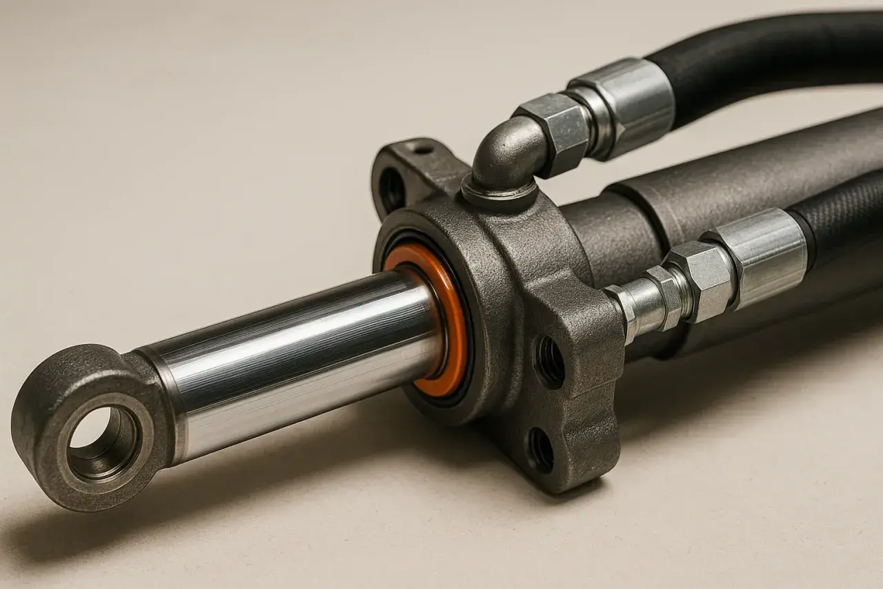
The rod end is the point where the cylinder stops being a pressure device and starts behaving like part of a machine linkage. It transfers linear force into a pin, a clevis, a threaded adapter, or a self-aligning joint, and that small interface often decides whether the cylinder runs smoothly or starts fighting the mechanism.
When the connection is wrong, the cylinder does not usually fail in a dramatic way on day one. It begins with side load, then the pin or bush wears unevenly, and after that the rod seal and bearing surfaces start paying the price. In practice, I treat the rod end as a load-transfer interface, not just a hardware detail, because the joint has to respect the motion path as much as the pressure rating.
Once you see it that way, the next step is comparing the actual connection families and deciding which one matches the machine rather than forcing the machine to adapt to the cylinder.
The main connection families I compare first
In most fluid power layouts, I would group the available rod-end connections into a few practical families. The exact naming changes from catalogue to catalogue, but the behaviour is familiar: some ends are built for compact threading, some for pinned pivoting, and some for deliberate self-alignment.
| Connection type | What it is | Best fit | Main advantage | Main trade-off |
|---|---|---|---|---|
| Threaded rod end | A male or female thread that screws into an adapter, coupler, or custom attachment | Compact assemblies, adjustable set-up, custom machinery | Simple, short, and easy to position during assembly | Needs secure locking and does little to forgive misalignment |
| Rod eye | A single eye with a pin passing through a mating lug | General pivoting linkages, modest articulation | Easy to inspect and widely understood by maintenance teams | Only tolerates limited angular movement before wear accelerates |
| Rod clevis | A forked end that captures a lug or pin between two cheeks | Heavy-duty linkages, compact pin joints, protected hardware | Sturdy and mechanically familiar in industrial and mobile equipment | Can bind if the linkage geometry is poor or the pin is oversized |
| Spherical rod end | A self-aligning joint with a spherical bearing, sometimes called a floating joint | Machines with misalignment, oscillation, or changing load angles | Best for absorbing angular error without forcing the rod to side-load | More expensive and introduces a wear element that must be maintained |
| Special adapter or welded end | A custom-machined or welded interface designed for one machine | Space-limited or unusual linkages | Can solve packaging problems that standard parts cannot | Higher engineering effort and less flexibility in service |
The terminology is not always clean. Some catalogues use terms such as rod eye, clevis eye, plain clevis, swivel head, or floating joint for closely related hardware, and I care more about the load path than the label. If the rod has to swing through a real arc, the shape of the joint matters more than the marketing name on the page, which is why motion should come next in the decision.
When motion and misalignment should drive the choice
A cylinder that works in a straight, guided push-pull motion can often get away with a simpler rod end. A cylinder that drives a rocker arm, a lever, or an attachment with an imperfect swing path cannot. That is the point where motion profile becomes the real selector.
Straight push-pull motion
If the linkage is well guided and the rod mainly sees axial force, a threaded end, rod eye, or rod clevis can be perfectly adequate. I would still want the joint to pivot freely, but I would not spend money on self-alignment that the machine does not actually need.
Arcs, swing links, and oscillation
Once the rod end is following an arc, the machine is asking for angular movement every cycle. In that case, a plain eye or clevis may work only if the geometry is tight and the stroke remains forgiving. If the side load starts creeping up, a spherical rod end becomes the cleaner answer because it lets the rod follow the motion instead of forcing the bearing surfaces to absorb the error.
Read Also: Hydraulic Cylinder Mounts: Avoid Costly Failures
When self-alignment earns its keep
I usually recommend a spherical or floating joint when the cylinder is mounted in a way that cannot stay perfectly square through the full stroke, or when the machine sees repeated reversals and the linkage shifts a little every time. The joint does not remove all wear, but it moves the wear into a controlled place instead of spreading it across the rod, seal, and pin bore. That trade-off is often worth paying for, especially in high-cycle industrial equipment.
That is also why a pin joint should not be used as a bandage for poor installation. It can tolerate some error, but it should not be expected to hide bad geometry, and that brings us to the specification details that matter before a cylinder is ordered or replaced.
Details I would check before I specify or replace one
When I am replacing a cylinder or designing around one, I do not start with the part number. I start with the actual hardware dimensions and the way the machine is built, because old equipment often mixes standards and the label on the previous unit may not tell the whole story.
- Thread form and direction - I verify the thread size, pitch, and whether the rod uses a male or female end, because a close-looking thread that is not identical will create trouble later.
- Pin diameter and bush fit - A pin that is too loose beats up the hole, while a pin that is too tight can make the joint bind and push unwanted load into the cylinder.
- Locking method - If the connection is threaded, I want a jam nut or equivalent retention that cannot unwind under vibration.
- Lubrication access - A joint that is hard to grease will usually be neglected, and neglected joints become expensive joints.
- Corrosion and contamination exposure - Washdown areas, outdoor plant, and dusty environments demand better surface protection and more careful material selection.
- Maintenance access - If the pin cannot be removed without stripping half the machine, the design is already making tomorrow harder than it needs to be.
- Standard compatibility - In UK industry I still see metric and imperial hardware living side by side, especially on imported equipment, so I never assume the rod end just from the cylinder bore.
Those checks sound basic, but they prevent most of the avoidable mistakes I see in the field. If the connection is chosen correctly on paper and still fails early, the problem is usually not the concept; it is the way the joint was applied.
The mistakes that shorten service life
The most common failures are usually quiet ones. They do not start with a broken rod; they start with wear, vibration, and poor alignment that no one wanted to revisit during installation.
- Using a threaded end without proper locking - A connection that slowly backs off is a design problem, not a maintenance surprise.
- Choosing a plain eye where the linkage needs self-alignment - The pin hole often becomes the sacrificial part, and it usually loses faster than people expect.
- Ignoring bushing wear - A worn bush can make a good cylinder look bad, because the real issue is the joint, not the hydraulic unit.
- Confusing rod-end hardware with a mounting style - A trunnion, for example, is a cylinder mounting arrangement, not a rod-end connection, so it solves a different problem entirely.
- Reusing damaged pins - Scoring, brinelling, or ovality means the contact pattern is already wrong, and the new build inherits the same weakness.
- Accepting visible side load as normal - If one side of the pin or eye is polishing while the other side stays dull, the rod end is telling you the geometry is off.
When I see those signs, I do not blame the cylinder first. I look at the linkage, the mounting points, and the maintenance history, because that is where the root cause usually lives. With that in mind, the most useful question is not which part looks strongest, but which one fits the machine cleanly from the start.
How I choose a rod-end connection on a real machine
My selection process is simple because the machines usually are not. I start with motion, then check how the load enters the joint, and only then think about cost or catalogue convenience.
- Map the motion path first - If the rod stays aligned and only pivots slightly, I stay with a simpler eye or clevis; if the path is messy, I move toward self-alignment.
- Check the load direction - A connection that sees shock, reversal, or bending needs more forgiveness than a joint that only sees clean tensile or compressive force.
- Confirm service access - If the team cannot inspect, grease, and remove the pin safely, I treat that as part of the design risk.
- Choose the simplest joint that survives the duty cycle - I prefer the least complicated option that still gives acceptable alignment, because every extra feature becomes another wear surface.
That last point is the one I keep coming back to. A more elaborate end fitting is not automatically better; it is only better if the machine genuinely needs the extra articulation or packaging help. In a lot of hydraulic systems, the best choice is the one that disappears into the mechanism and just keeps working.
The final checks that make the choice hold up in service
Before I release a design or approve a replacement, I do one final pass and ask a few blunt questions. Is the joint positively locked? Can the pin be removed without a fight? Will the rod end still align cleanly after months of wear and vibration? If the answer to any of those is weak, I know the machine will be paying for it later.
The rod end is a small detail with an outsized effect. Get it right and the cylinder feels predictable, quiet, and easy to maintain; get it wrong and even a high-quality cylinder will look unreliable. If you are choosing between rod eyes, clevises, threaded ends, or a self-aligning joint, I would always start with the motion you actually have, not the hardware you happen to have on the shelf.