Ethernet is easiest to understand when you split it into two jobs: moving electrical or optical signals across the medium, and moving frames between devices on a local link. That split is what people usually mean when they talk about ethernet layers, and it is the part that matters when you are troubleshooting a switch port, choosing cabling for a factory cell, or deciding whether a network needs deterministic timing. In industrial and IoT environments, I usually find that the real question is not “what is Ethernet?” but “which layer is failing?”
The practical split is physical transmission below and frame handling above
- Ethernet mainly sits across OSI Layer 1 and Layer 2; IP and applications run above it.
- Layer 1 deals with signals, cabling, optics, reach, speed, duplex and noise tolerance.
- Layer 2 handles MAC addresses, frames, VLAN tags, priority and error detection.
- Modern switched Ethernet is usually full duplex, so collisions are mostly a historical concern.
- In industrial networks, TSN and VLANs change behaviour at Layer 2, not the cable itself.
- Fast troubleshooting starts at the wire, then the frame, then the higher-layer protocol.
What Ethernet actually covers
The cleanest way to think about Ethernet is to treat it as a local-link technology, not a full network stack. It gives devices a way to transmit bits reliably over a medium and a way to package those bits into frames that can be switched from one port to another. Everything beyond that, including routing and application logic, sits on top.
That matters because the word “Ethernet” is often used too loosely. In practice, it spans a physical transport layer and a data-link layer, while the upper layers belong to IP, TCP, industrial protocols or the application itself. I prefer to separate those responsibilities early, because it avoids the common mistake of trying to solve a cabling fault with routing settings, or a VLAN issue with a cable tester.
| OSI layer | Ethernet’s role | What you usually check |
|---|---|---|
| Layer 1 | Moves bits as electrical or optical signals | Cable type, optics, speed, duplex, length, interference, link lights |
| Layer 2 | Moves frames on the local link | MAC addresses, VLANs, frame counters, CRC errors, switch forwarding |
| Layers 3-7 | Not owned by Ethernet itself; carried inside Ethernet frames | IP addressing, routing, transport behaviour, application latency |
This split is especially useful in factories and smart manufacturing systems, where a single network may carry PLC traffic, vision data, maintenance access and sensor telemetry. Once you see that separation clearly, the physical layer becomes the right place to start.
The physical layer is where bits become signals
At Layer 1, Ethernet is concerned with the medium itself: copper, fibre or another physical channel. This is where the signal is encoded, transmitted, received and decoded. IEEE 802.3 defines the physical behaviour for different speeds and media types, which is why the same logical network can run over twisted pair in one cabinet and fibre between buildings without changing the higher-layer design.
I start with the wire here because most “network” failures are actually signal problems. A healthy physical layer needs the right cable category, good termination, correct optics or transceivers, negotiated speed and duplex, and enough margin for the installed distance. On twisted pair, 100 metres is still the usual planning limit. That is fine in an office rack, but it becomes a real constraint in a plant where devices sit around conveyors, skids and control cabinets.
What tends to matter most in industrial environments
Industrial sites are harder on copper than a typical office. Motors, drives, welders and poorly grounded cabinets can add noise that turns a perfectly valid design into an unstable link. If I have a choice, I prefer fibre for long runs or electrically noisy areas, and shielded copper only when the installation quality is controlled. The cable is not the only variable, but it is usually the first one worth checking.
- Use fibre when electromagnetic interference is a serious risk.
- Respect bend radius and termination quality, especially in tight enclosures.
- Check for negotiated speed drops, flapping links and rising CRC counters.
- Do not assume auto-negotiation will save a badly matched or damaged link.
Why duplex and encoding still deserve attention
Modern switched Ethernet is typically full duplex, so the old collision-based model is mostly historical on new installations. That said, the standard still defines shared-medium behaviour, and mismatched duplex settings can still cause ugly symptoms. If a link is repeatedly dropping frames or running far below expectation, I look at the physical negotiation before I blame the application.
Once the signal path is stable, the next layer up is where Ethernet starts to behave like a real local network rather than just a transport medium.
The data link layer is where frames and MAC addresses live
Layer 2 is where Ethernet becomes useful for switching. This is the layer that defines frames, MAC addressing, VLAN tagging and frame integrity checks. A switch does not need to understand the whole payload to move traffic correctly; it mainly needs to know where the frame came from, where it is going and whether the frame arrived intact.
In plain terms, the physical layer moves bits, but the data link layer gives those bits structure. That structure is what lets a network stay organised when multiple devices share the same infrastructure.
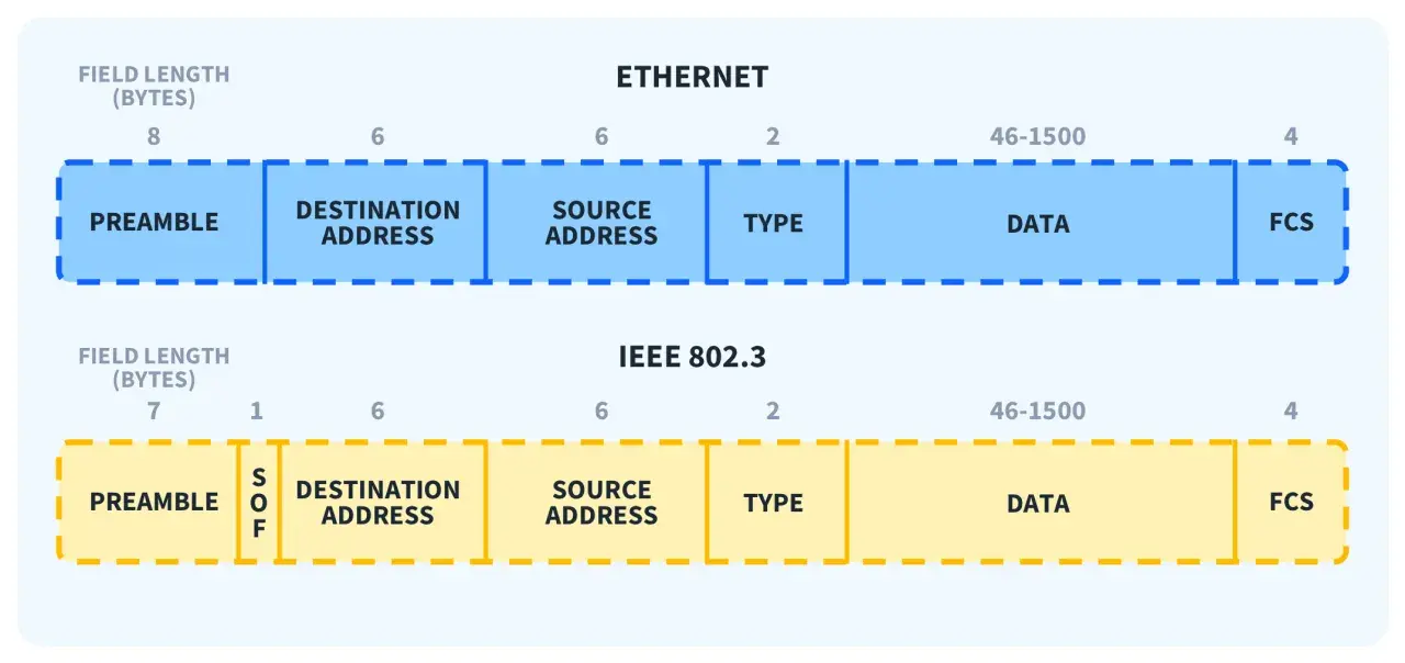
| Frame field | Typical size | Why it matters |
|---|---|---|
| Preamble and start frame delimiter | 8 bytes total | Helps the receiver lock on and recognise the start of a frame |
| Destination MAC address | 6 bytes | Tells the local network where the frame is going |
| Source MAC address | 6 bytes | Identifies the sender on the local link |
| 802.1Q VLAN tag | 4 bytes, optional | Separates traffic and can carry priority information |
| EtherType or length | 2 bytes | Indicates what the payload contains or how long it is |
| Payload | Usually 46 to 1500 bytes | Carries IP, ARP, IPv6 or industrial protocol data |
| Frame check sequence | 4 bytes | Detects corruption in transit |
MAC and LLC are not the same thing
Strictly speaking, classic IEEE 802.3 separates Layer 2 into MAC and LLC sublayers. The MAC sublayer is the part most engineers touch in day-to-day work: addressing, switching, frame handling and error counters. LLC is the thinner control layer above it, which helps identify or multiplex upper-layer protocols. In most modern deployments, people talk about the MAC path because that is where configuration and troubleshooting usually happen.
Read Also: DWDM Explained - Maximize Fiber Capacity & Avoid Costly Errors
VLANs belong here for a reason
VLAN tagging is also a Layer 2 function, and it is easy to underestimate its effect. A device may be physically connected and still be logically invisible because the switch port is in the wrong VLAN, the trunk is missing a tag, or the endpoint does not expect tagged traffic. That is one of the fastest ways to waste time on a “network outage” that is really a framing problem.
Once you understand Layer 2, the rest of the stack becomes easier to place: Ethernet carries the traffic, but it does not own the meaning of that traffic.
How Ethernet fits with the rest of the stack
Ethernet does not route traffic between networks. It delivers frames on the local link, then leaves the higher-layer protocol to do its own job. IP, ARP, IPv6, TCP, UDP and industrial application protocols all ride inside Ethernet frames, which is why a healthy link is not the same thing as a healthy application path.
I find this distinction especially useful when a machine looks “online” but still fails at the control or application level. A switch may be forwarding frames correctly, yet the routing table, firewall policy or application session can still be wrong.
- Switches care mainly about MAC addresses, VLANs, link aggregation and Layer 2 forwarding.
- Routers care about IP networks and the next hop between subnets.
- Firewalls often inspect IP, ports and application behaviour, depending on the policy.
- Industrial controllers usually care about timing, segmentation and predictable delivery as much as raw speed.
That is why a plant network can be physically perfect and still fail operationally. A PLC might sit on the right switch, but if the control VLAN, ACL or route is wrong, the device is effectively isolated. The same logic applies to maintenance laptops, historians and vision systems. The link is only one piece of the path.
Why industrial and TSN networks care about the layers
Industrial Ethernet pushes the layer split into real production consequences. A packaging line, motion-control loop or remote I/O island cannot tolerate the same delay variation that a normal office workstation can. That is where Time-Sensitive Networking matters. TSN extends Ethernet with deterministic behaviour, including bounded latency, low delay variation and lower packet loss, using IEEE 802.1 mechanisms such as time synchronisation, traffic scheduling and frame replication.
The important point is that TSN changes how Layer 2 behaves; it does not replace the physical layer underneath it. You still need correct cabling, stable switches and a medium that can carry the signal cleanly. TSN makes the delivery more predictable, but it does not rescue a bad installation.
- Use standard best-effort Ethernet when timing is not strict.
- Use VLANs when you need segmentation, priority or cleaner fault isolation.
- Use TSN when deadlines, synchronisation and jitter matter more than average throughput.
- Keep the physical design aligned with the timing target, because deterministic software cannot fix poor cabling.
For industrial automation and IoT projects, that is the real design question: do you need simple connectivity, segmented connectivity or deterministic connectivity? Once you answer that, the layer choices become much easier to defend.
Mistakes that waste time in troubleshooting
The most expensive Ethernet problems are usually the ones where teams look in the wrong layer for too long. I have seen good engineers chase routing, application services and device firmware when the fault was sitting in the cable tray, the trunk port or a duplex mismatch. A disciplined layer-by-layer check saves hours.
- Blaming IP for a physical fault when the link is actually flapping or dropping errors.
- Ignoring VLAN tags and assuming a device is “connected” just because the light is on.
- Forgetting negotiated speed and duplex on older or mixed-vendor equipment.
- Assuming all copper runs are equal when noise, grounding and termination quality differ.
- Enabling jumbo frames casually without confirming every switch, NIC and endpoint supports them.
- Assuming low latency means low jitter when deterministic control needs both.
If I see CRC errors, flapping links or sudden speed renegotiation, I treat that as a Layer 1 warning first. If the link is stable but endpoints cannot talk, I move to Layer 2 and check MAC learning, VLAN membership and trunk configuration. Only after that do I spend time on IP, routing or the application itself.
The order I use when Ethernet starts misbehaving
The best mental model is simple: signal first, frame second, protocol third. That order matches how Ethernet actually works, and it usually leads you to the fault faster than jumping straight to the top of the stack. On a well-run industrial network, the cable plant, switch fabric and Layer 2 design should all be boring. That is a good thing.
When I design or audit a network, I ask three questions in order: can the medium carry a clean signal, can the frame reach the right device, and can the higher-layer protocol make use of that frame without delay or ambiguity? If you keep that sequence in mind, Ethernet stops feeling vague and starts behaving like the layered system it really is. In practice, that is the difference between guessing and diagnosing.