The physical layer is where network data becomes an electrical, optical, or radio signal that can actually move. In industrial automation, smart manufacturing, and IoT, that base level often decides whether a link is stable, noisy, or dead on arrival. I will break down what Layer 1 does, how the main media differ, and how I would diagnose problems in real installations.
The Layer 1 details that matter most on real networks
- It turns bits into signals and defines how those signals travel across copper, fibre, or air.
- It controls timing, bit rate, duplex behaviour, and basic signalling quality.
- The medium and hardware often matter more than the protocol name on the box.
- Most stubborn faults start with cables, connectors, transceivers, interference, or bad alignment.
- In factories and IoT systems, the best design usually balances distance, noise, mobility, and maintenance effort.
What Layer 1 actually does
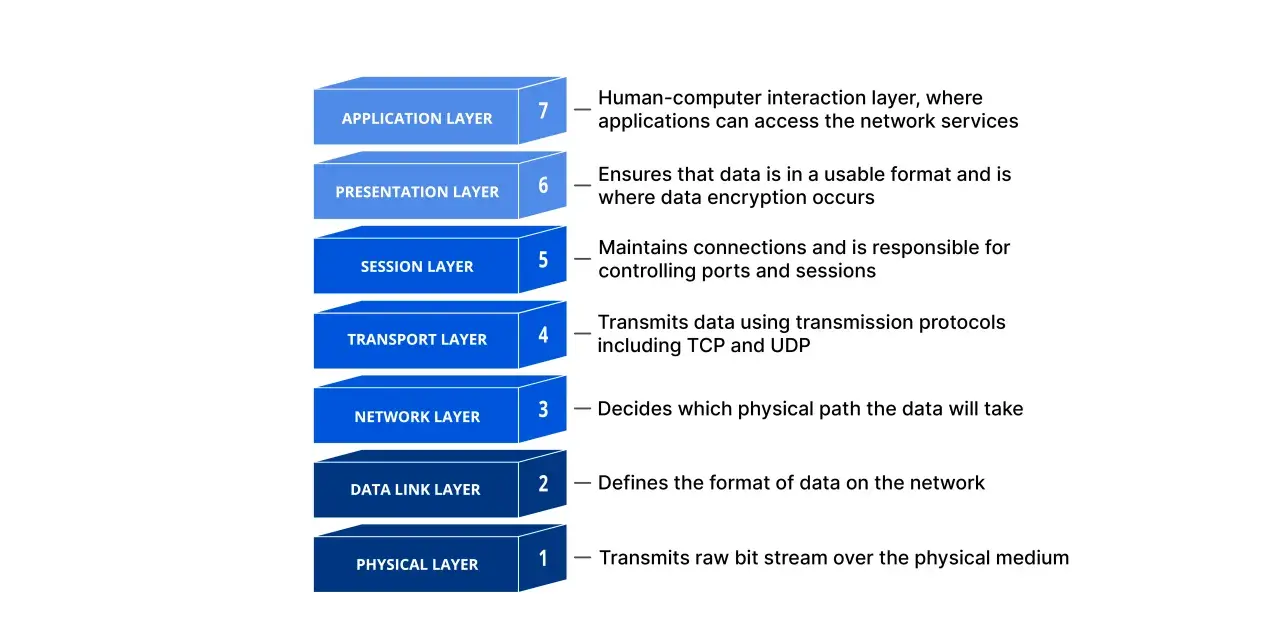
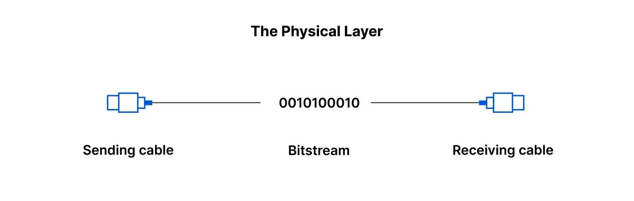
Layer 1 is responsible for the most basic job in networking: carrying raw bits as signals. IBM’s description is the one I keep coming back to because it keeps the focus on timing and transport, not on addresses or packets. This layer defines how data is encoded on the medium, how fast it moves, how devices stay synchronised, and whether the connection behaves as simplex, half duplex, or full duplex.
- Bit rate sets how much data can move per second.
- Synchronisation keeps sender and receiver aligned at the bit level.
- Transmission mode determines whether traffic can move one way or both ways at once.
- Topology describes how devices are physically arranged, such as star or mesh layouts.
- Encoding and signalling decide how bits become voltage changes, light pulses, or radio waves.
The practical takeaway is blunt: if the signal path is poor, the rest of the stack never gets a fair chance to work. Once that is clear, the next question is not which protocol you run, but what actually carries the signal.
The media and hardware that carry the signal
At this level, the choice of medium is not a minor detail. Copper, fibre, and wireless each solve different problems, and each introduces its own limits. You also have the hardware around the medium, including NIC PHYs, transceivers, connectors, patch panels, and repeaters. In other words, the link is only as good as the weakest part of the path.
| Medium | Where it shines | Trade-off | Typical use |
|---|---|---|---|
| Twisted-pair copper | Low cost, easy termination, common hardware, Power over Ethernet support | More exposed to electromagnetic noise and distance limits | Office links, machine-level runs, short industrial connections |
| Fibre optic | Long reach, high bandwidth potential, strong immunity to EMI | Higher optics cost and more care needed with handling and cleanliness | Backbones, inter-building links, noisy plant areas |
| Wireless | Mobility, fast deployment, fewer fixed cables | Shared spectrum, interference, less deterministic latency | Mobile devices, sensors, temporary equipment, hard-to-wire zones |
| Serial or fieldbus signalling | Simple, robust over certain distances, often resilient in harsh environments | Lower throughput and less flexibility than modern Ethernet links | Legacy equipment, drives, long noisy runs, specialised control gear |
In the physical layer, the medium matters more than the protocol: a perfect packet format cannot rescue a noisy cable, a damaged connector, or a weak transceiver. That is why I treat hardware choice as a design decision, not an installation afterthought. Once you see it that way, the differences between Ethernet, Wi-Fi, and industrial links become much easier to judge.
Why Ethernet, Wi-Fi, and industrial links behave so differently
Ethernet, Wi-Fi, and serial or fieldbus links all begin at Layer 1, but they make very different compromises. Ethernet over twisted pair or fibre is usually the easiest to standardise and troubleshoot. Wi-Fi gives you mobility and faster deployment, but it shares spectrum and has to live with interference. Industrial serial links such as RS-485 still earn a place when distance, electrical noise, or simplicity matter more than raw bandwidth.
- Ethernet is usually the best choice when you want predictable behaviour and easy maintenance.
- Wi-Fi is useful when movement or retrofit constraints make cabling impractical.
- Serial and fieldbus systems remain valuable when the job is narrow, tough, and well understood.
- Hybrid designs are common in factories: fibre for the backbone, copper at the machine, wireless for mobile assets.
In many 2026 deployments, that hybrid approach is the sensible one. I would rather match the link to the environment than force one technology to do everything badly. That mix is also why the same symptom can have very different causes, which is where fault-finding starts.
How I isolate faults before blaming protocols
Cloudflare is right that the OSI model still earns its keep in troubleshooting, because it helps narrow a problem to one layer instead of guessing blindly. When I look at a flaky link, I start with the obvious Layer 1 checks before I touch VLANs, IP addresses, routing, or application settings.
| Symptom | Likely Layer 1 cause | First check |
|---|---|---|
| No link light | Bad cable, unplugged connector, dead port, failed SFP or NIC | Reseat both ends and try a known-good cable or transceiver |
| Link flaps up and down | Loose termination, dirty fibre end, vibration, marginal signal | Inspect the connector, clean optics, and check the physical route |
| CRC errors or corrupted frames | Noise, damaged pairs, poor shielding, excessive bend radius | Swap the cable and check for EMI or installation damage |
| Slow throughput | Duplex mismatch, retransmissions, weak signal quality | Verify negotiated speed and duplex on both ends |
| Intermittent drops under load | Heat, movement, marginal optics, unstable power to the endpoint | Test while the system is busy, not only on a quiet bench |
- Check LEDs, port status, and obvious alarms first.
- Swap the cable, patch lead, or SFP with a known-good spare.
- Verify speed, duplex, and auto-negotiation settings.
- Inspect bend radius, connector cleanliness, and cable routing.
- Look for noise sources, vibration, moisture, or temperature stress.
When a problem survives a simple swap, I stop assuming it is “just software” and look harder at signal quality and the environment. That approach saves a lot of time in plants, warehouses, and edge sites where physical stress is often the real culprit. From there, the design choices that prevent the fault become much easier to make.
Choosing a reliable design for factories and IoT deployments
In UK factories and distribution centres, the safest pattern is often fibre for backbones and inter-building runs, shielded twisted pair for short machine links, and wireless only where mobility or temporary equipment justifies it. The real trade-off is not speed versus speed; it is margin versus convenience. Plenty of links work on day one and then fail after a machine is moved, a cable is bent too tightly, or a panel fills with noise.
- Use fibre when EMI is heavy, distances are longer, or you need cleaner isolation between areas.
- Use copper when you need Power over Ethernet, short runs, or low-cost installation.
- Use wireless when mobility matters more than deterministic latency.
- Standardise spare parts such as patch cords, optics, and transceivers so maintenance is faster.
- Document the route so future changes do not create hidden bends, stress points, or unplanned exposure to noise.
I also think it is worth being conservative with installation quality. Clean terminations, sensible bend radii, and decent strain relief are not glamorous, but they reduce a surprising amount of downtime. If Power over Ethernet is part of the design, I would pay even closer attention to cable quality and voltage drop, because the same path now carries both data and power. That leads to the last thing I would prioritise on any new build.
The choices that keep Layer 1 boring
My goal on a good network is not to make the lowest layer impressive; it is to make it invisible. That happens when the signal path has enough margin, the medium suits the environment, and the maintenance team can service it without improvisation. The best networks are often the ones nobody has to think about during a shift.
- Choose the medium for the environment first, not the headline speed.
- Budget for spare optics, patch cords, and transceivers.
- Test under production load, not only in a quiet lab.
- Re-check links after maintenance, machine moves, or panel changes.
- Treat signal quality as an operational metric, not a one-time install detail.
When the signal path is clean, stable, and easy to maintain, the rest of the stack gets to do its job instead of compensating for a weak foundation. That is the practical value of getting Layer 1 right in industrial networking.