I will also separate the wiring pattern from the cable category, because pinout and performance are not the same decision. That distinction matters in patch panels, wall outlets, CCTV lines, PoE devices, and any network where you want the link to work first time and stay stable.
The practical points to keep in mind before you terminate a run
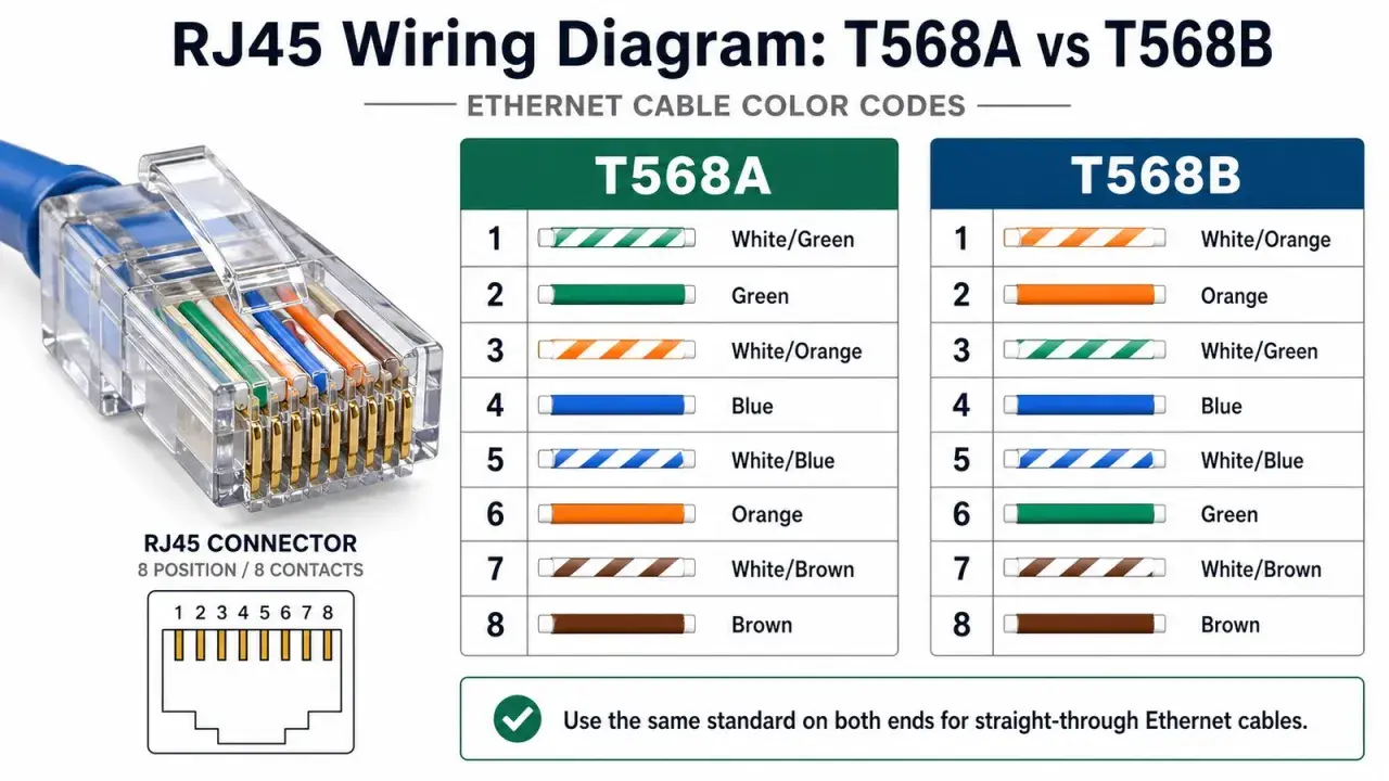
- T568B is a wiring standard, not a different physical cable.
- The only change versus T568A is the position of the green and orange pairs.
- Use the same scheme on both ends for a straight-through link.
- Keep the total copper channel within the 100 m limit.
- Choose Cat5e, Cat6, or Cat6A for bandwidth and distance, not because of the B label.
What T568B means in practice
At its simplest, T568B tells you how the eight conductors inside a twisted-pair Ethernet cable should land on an 8P8C modular connector, the plug most people still call RJ45. The jacket, the copper, and the connector hardware can all be the same; what changes is the order of the coloured pairs at the termination.
The wiring pattern is easy to read once you stop thinking of it as a mystery code. In B wiring, the orange pair is placed on pins 1 and 2, the green pair on pins 3 and 6, and the blue and brown pairs stay in their usual positions. That makes it a neat, repeatable scheme for patch panels, keystone jacks, and field-terminated plugs. Once that is clear, the real question is not what the letters mean, but how B compares with the alternative.
| Pin | T568B colour | Pair |
|---|---|---|
| 1 | White/orange | Orange pair |
| 2 | Orange | Orange pair |
| 3 | White/green | Green pair |
| 4 | Blue | Blue pair |
| 5 | White/blue | Blue pair |
| 6 | Green | Green pair |
| 7 | White/brown | Brown pair |
| 8 | Brown | Brown pair |
How T568B differs from T568A
The two wiring schemes use the same copper pairs and deliver the same electrical outcome. The only difference is which colour pair goes to pins 1 and 2, and which pair goes to 3 and 6. For modern Ethernet, that means the choice is mostly about consistency, documentation, and matching whatever the rest of the site already uses.
| Point | T568A | T568B |
|---|---|---|
| Pin 1 and 2 | Green pair | Orange pair |
| Pin 3 and 6 | Orange pair | Green pair |
| Electrical performance | Same | Same |
| Typical decision | Use it when a site already standardises on A | Use it when a site standardises on B |
If both ends match, the cable is straight-through. If one end is A and the other is B, you have a crossover cable. On modern switches and routers that is less important than it used to be, because auto-sensing handles many mismatches, but I still treat mixed terminations as a mistake unless a legacy device explicitly needs them. In the UK, the same rule applies: pick one scheme and stay consistent across the room, the rack, and the patch leads. That consistency becomes much more valuable once the cable disappears into walls and containment.
Where I would use it in an office, factory, or IoT build
In practice, the B scheme is useful anywhere you want predictable copper terminations and easy handover between contractors. I see it most often in office switches, patch panels, access points, IP cameras, industrial gateways, PLC cabinets, and building management systems.- Patch panel to switch links: the most common place where consistent termination saves time during moves and changes.
- Wall outlet to workstation or device: useful because the socket, patch lead, and documentation all line up.
- PoE endpoints: cameras, phones, and access points benefit more from good termination quality than from any debate about A versus B.
- Industrial enclosures: control rooms and cabinets need repeatable cabling so troubleshooting is not guesswork later.
If I am wiring a site with multiple installers, my priority is not winning the A-versus-B argument. It is making sure every termination in the channel follows the same scheme and is labelled clearly enough that the next engineer can trace it without opening every drawer in the rack. From there, the next step is not more theory but a clean termination and a proper test.
How to terminate and test it without creating hidden faults
The physical work is straightforward, but small mistakes create problems that only show up after the cable is back in the wall. My process is simple: keep the pair twist as close to the termination as possible, land each conductor in the correct slot, and test the run before it goes live.
- Confirm the scheme before you strip anything.
- Remove only enough jacket to seat the pairs cleanly.
- Preserve the twist in each pair instead of untwisting half the cable.
- Seat the conductors firmly in the punch-down block or modular plug.
- Use the proper punch-down or crimp tool once, not repeatedly.
- Test for continuity, pair order, and obvious shorts before final handover.
Split pairs are a mistake I still see too often: the cable looks right at a glance, but the conductors from one twisted pair have been placed into different pair positions. A basic continuity tester may not always expose the full penalty, so for business-critical or industrial links I prefer a proper cable certifier if the budget allows it.
That testing step is where a lot of rushed installations fail. A link can still light up while quietly negotiating at a lower speed or behaving badly under PoE load, so the result you want is not just "it works" but "it passes the right test for the cable category and distance". Once that is under control, the cable grade becomes the next real decision.
Which cable category I would choose before I even think about the wiring colour
The label on the connector does not tell you whether the cable is suited to the job. For that, you need the category: Cat5e, Cat6, or Cat6A. If I am planning a new run, I choose the category first and the termination scheme second.
| Category | Best fit | Strengths | Trade-offs |
|---|---|---|---|
| Cat5e | Basic office devices, printers, and many IoT endpoints | Low cost, easy to terminate, still widely deployed | Less headroom for demanding new builds |
| Cat6 | General office networking and moderate PoE use | Better noise margin than Cat5e, good all-round choice | Stiffer than Cat5e and not always the best route for future 10 GbE |
| Cat6A | 10 GbE planning, PoE-heavy installs, and higher-noise environments | Best common copper choice for future-proofing, supports 10 GbE to 100 m | Bulkier, less flexible, and usually more expensive |
For industrial automation and IoT, I would usually lean toward Cat6A when the run is new and the budget allows it, especially if the cable will live near motors, drives, or dense power distribution. Cat5e still has a role, but it is a decision I make deliberately rather than by habit. The point is to match the medium to the site, not to assume the pinout will rescue a marginal cable. From there, the final trap is usually not the standard itself, but the small mistakes that look harmless during installation.
The checklist I use before I close a run
- Pick one wiring standard and use it everywhere in the same installation.
- Label both ends, including the patch-panel port and the outlet or device side.
- Keep the copper channel within the 100 m limit, including patch leads.
- Use the right category for the speed, PoE load, and environmental noise you expect.
- Test every run, even if the link light comes on immediately.
If I had to reduce the whole topic to one sentence, it would be this: T568B is a termination standard, not a performance upgrade, and the cable only behaves well when the wiring scheme, the category, and the test results all agree. Get those three parts aligned, and the network stops being fussy about the details you cannot see from the outside.