
Industrial automation teams usually do not struggle with whether a sensor can send data; they struggle with whether the same network can do it without becoming a weak point. This article breaks down the safety extension for IO-Link, how it fits into a machine network, what actually makes the communication trustworthy, and what I would check before treating it as part of a real safety function. The practical angle matters here: if you are designing compact sensor and actuator networks, the difference between “connected” and “safety-capable” is the difference between convenience and a valid risk reduction strategy.
What matters most before you design the network
- Standard IO-Link is a robust point-to-point device link, but it is not a safety protocol on its own.
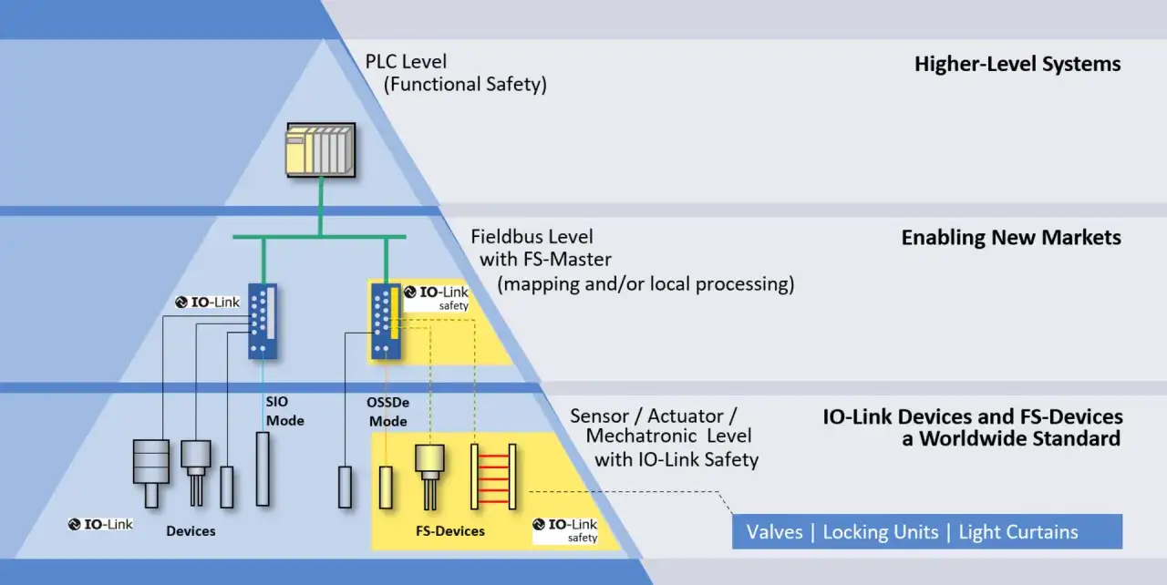
- The certified safety extension adds FS masters and FS devices, with the safety function carried in a separate, supervised layer.
- The communication model is still compact and familiar, often using the same 3- or 5-wire cabling approach as standard IO-Link.
- Mixed communication can carry standard diagnostics and safety-related data on the same device, which is useful in modern machines.
- In practice, the safe link still has to sit inside a wider safety architecture, usually with a safety PLC or another higher-level safety profile.
- The biggest risk is assuming that safety-rated devices automatically make the whole machine safe without a proper validation chain.
What standard IO-Link can and cannot guarantee
I usually start with a blunt distinction: standard IO-Link is excellent at device communication, but it does not turn every connected sensor into a safety device. It is a serial, bidirectional, point-to-point link used for process data, parameterization, and diagnostics. That is useful, but it is not the same thing as a functionally safe communication path.
The current PI material puts the safety extension on a formal footing with IEC 61139-2 and TÜV SÜD certification. That matters because safety is not a marketing feature; it is a certified design discipline. In the real world, that means only the certified safety-capable parts belong in the safety function, while ordinary IO-Link stays in its usual role.
| Aspect | Standard IO-Link | Safety extension | Why it matters |
|---|---|---|---|
| Primary role | Process data, diagnostics, parameterization | Functional safety communication | You should not mix convenience data with the safety case |
| Device types | IO-Link sensors and actuators | FS masters and FS devices | The hardware set changes, not just the software label |
| Cabling model | Standard 3-wire sensor wiring | Same basic wiring approach, often 3- or 5-lead | Retrofits stay practical |
| Safety status | Not safety-rated by default | Certified for the safety function | Only the certified chain can justify a safety claim |
| Best use | Standard industrial networking | Safety-relevant sensors, actuators, and safe stops | Choose the layer that matches the risk |
Once you separate those roles, the architecture question becomes much easier to answer. The next issue is where the safety layer sits in the machine network and how it reaches the controller.
How the safety extension fits into a machine network
The cleanest way to think about it is this: the safety-capable IO-Link segment is still a point-to-point device link, not a fieldbus that tries to do everything. The official integration material describes it as a solution that can be integrated into higher-level functional safety communication profiles when needed, rather than a replacement for the machine’s main safety backbone.
That is why the architecture usually includes an FS master at the edge, an FS device in the field, and then a safety controller above them. In one of the most useful demo scenarios I have seen documented, a failsafe PLC talks to IO-Link Safety masters over PROFINET and PROFIsafe. That is the right mental model for many plants: the device layer stays compact, while the safety decision still lives in the controller.
There is also a practical upside here for UK machine builders and integrators. The same physical device can often carry ordinary device data and safety-related data in a more orderly way than a bundle of separate hardwired points, which makes cabinet layout and maintenance easier. For the engineer, the attraction is not novelty. It is less wiring without giving up a validated safety structure.
Mixed communication is especially important. In that mode, safety-oriented and standard data can be exchanged with the same device at the same time. That is useful for things like door locks, control-and-signalling devices, and smart drive peripherals, because the non-safety functions can keep behaving normally while the safety function is handled separately. Once that separation is clear, the next step is to look at what actually makes the channel trustworthy.
The checks that make the channel trustworthy
The public IO-Link Safety material leans on the familiar functional-safety idea of a black channel. In plain English, that means the transport path itself is not trusted to be inherently safe. Instead, safety is enforced by the safety layer and the controller logic around it. That is a sensible model for industrial networking, because it assumes faults can happen and designs for them rather than pretending they will not.
From the available material, several practical mechanisms stand out. The safety communication supports cyclic and acyclic data, which is important because maintenance teams still need diagnostics even when the safety function is active. It also describes OFF-state behavior and test pulses for certain sensor-style interfaces, which helps detect faults instead of silently accepting them. For classic wiring patterns, the specification also points to a 2-channel OSSD interface option, which gives a bridge to more traditional safety hardware.
Two more details matter in day-to-day engineering. First, device engineering still uses the normal IO-Link logic through the IODD, but a dedicated safety tool and a standardized Device Tool Interface can be used when the device needs safety-specific parameters. Second, pre-configuration outside the system is supported, which means you can validate settings before the hardware is fully installed. I like that because it reduces commissioning surprises, and commissioning surprises are expensive.
So the protocol side is not just about “making data safer.” It is about supervising timing, state, and configuration so that any serious fault pushes the system toward a safe reaction instead of a dangerous one. That matters most in the applications where the safety function is close to the device itself.
Where it earns its place on the plant floor
The best use cases are the ones where compact wiring, diagnostics, and local safety behavior all matter at the same time. Think of light curtains, emergency-stop devices, door locks, control-and-signalling boxes, safe drives, and smart safety light grids. Those are exactly the kinds of components that benefit from a dedicated safety layer on top of a familiar device network.
One of the strongest arguments for the technology is that it can handle several analog measurements safely and let the controller decide whether to switch off or stop. That is more useful than it first sounds. In a compact machine cell, the ability to collect richer device data while still using a certified safety path can reduce the amount of hardwired point-to-point logic you need to maintain.
I would treat the extension as especially attractive in three situations:
- Compact machines where cabinet space and cable routing are tight.
- Modular systems where devices are replaced or reconfigured often.
- Applications that need both diagnostics and a genuine safety function at the same device.
There are also situations where it is not the best answer. If you only need one or two simple hardwired safety actions, the extra architecture may be unnecessary. If the machine has a very wide safety zone or a simpler safety chain is easier to validate, I would not add network complexity just for the sake of it. That is why the specification step matters so much.
What I would verify before I buy hardware
I would not commit to hardware until I had checked five things.
- Certification scope - confirm that the exact master, device, and stack you plan to use are certified for the safety function, not merely compatible with standard IO-Link.
- Integration path - confirm how the device layer reaches the higher-level safety controller, especially if the machine already uses PROFINET, PROFIsafe, or another functional safety communication profile.
- Engineering workflow - check whether the project will use IODD-based engineering, a dedicated safety tool, and the standardized tool interface for safety parameters.
- Commissioning method - verify whether offline pre-configuration and auto-parameterization are supported, because that saves time when devices are swapped or tested off-line.
- Fault handling - make sure the safe state, reset behavior, and diagnostic visibility are documented in a way your safety validation team can actually use.
The practical mistake I see most often is treating a safety-capable device as if it automatically solves the whole machine. It does not. The device is only one part of the chain. The software logic, the controller, the fieldbus integration, the parameter management, and the validation records all matter just as much.
That is also why I prefer projects that keep standard data and safety data clearly documented even when they share the same physical device. The architecture can be elegant, but the paperwork still has to be traceable. Once that discipline is in place, the remaining design work becomes much easier to defend.
The design choices that save rework later
If I had to reduce the whole topic to one sentence, it would be this: use the safety extension where it genuinely simplifies the machine, not where it merely sounds modern. The strongest designs keep the risk assessment, the network architecture, and the commissioning plan in the same conversation from the start.
- Prefer devices with clear diagnostics and a documented replacement process.
- Keep the safety function separate from ordinary device logic, even when both travel over the same physical connection.
- Use the simplest validated safety path that meets the required stop time and coverage.
- Test configuration recovery and fault reactions before the machine goes live.
That is the real value of IO-Link-based functional safety: not just safer communication, but a more manageable way to build, commission, and maintain compact industrial networks. If you get the architecture right early, the safety layer becomes an asset instead of an integration headache.